


10
REPAIR INSTRUCTIONS
Note: Always take time to lubricate all metal and nonmetal parts with a light film of oil before
reassembly. This step will ensure proper fit, at the same time protecting the pump's non-
metal parts (i.e., the elastomers) from cutting and scoring.
To Check Valves
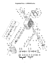
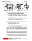
1. Screw-out inner hexagon screws (48A) with an allen wrench. Remove discharge plugs (48) with a screw driver.
Check O-Rings (48B) on discharge plugs and replace as necessary.
2. Pull out Pressure Ring (48C). Remove the Spring Tension Cap (47F) from the discharge Valve Plate (47D)
lying underneath by screwing in the 10mm screw. Take out the Valve Spring (47E) and Valve Plate (47D). Pull
out the Discharge Valve Seat (47C) by means of slide hammer. Check sealing areas of the Valve Plate (47D)
and the Valve Seat (47C) for damage and replace worn parts. Check O-Rings (47A and 47B) and replace as
necessary.
3. Screw Spacer Pipe (46G) out of the Spring Tension Cap (46F) located in the suction valve lying underneath.
Remove the Suction Valve Assembly (46) by screwing in a 10mm screw. Check O-Rings (46A and 46B) and
replace as necessary. If the Suction Valve Seat (46C) remains in the Valve Casing (43), remove it with a slide
hammer. Check the sealing areas of the Suction Valve Plate (46D) and the Suction Valve Seat (46C) for
damage and replace worn parts.
4. After reassembling the above items, tighten the Inner Hexagon Screws (48A) to 35 ft.-lbs.
To Check Seals and Plunger Pipes
1. Loosen the eight Inner Hexagon Screws (49) and pull of the Valve Casing (43) to the front. Pull Seal Sleeves
(35) out of the guides in the crankcase and over the plunger pipes (29B). Remove Sleeve Support Ring (41),
Sleeves (40) and Grooved Rings (36). Replace worn parts as necessary.
2. If a Plunger Pipe (29B) is worn out, loosen the Tension Screw (29C) and pull off the Plunger Pipe to the front.
Clean the contact surfaces of the Crosshead Assembly (25) thoroughly. Place the new plunger pipe carefully
through oiled seals back into the seal case. Check O-Rings (35A and 35B) on the Seal Sleeves (35) and
replace as necessary.
3. Push the Seal Sleeves (35) together with the Plunger Pipe (29B) back into the crankcase guide. Turn the
crankshaft (22) carefully until the Crosshead Assembly (25) comes up against the Plunger Pipe. Put a new Oil
Scraper (29D) onto the Tension Screw (29C). Cover the thread of the Tension Screw and the Oil Scraper and
apply a liquid adhesive such as Lock-Tite. Tighten Tension Screw to 26 ft.-lbs..
Important!!
Do not get any adhesive between the Plunger Pipe (29B) and the Centering Sleeve (29A). The
Plunger Pipe should not be strained by excessive force on the Tension Screw (29C) or through dam-
age to the front surface of the Plunger. If these conditions are ignored, the Plunger Pipe will prob-
ably break.
4. Tighten the Inner Hexagon Screws (49) to the Valve Casing (43) to 85 ft.-lbs.