


9
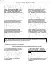
NOTE: Always take time to lubricate all metal and nonmetal parts with a light film of oil before reassembly.
This step will ensure proper fit, at the same time protecting the pump nonmetal parts (i.e., the elastomers) from cutting
and scoring.
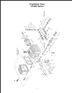
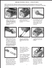
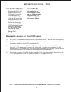
1. With a 22mm socket
wrench, remove the (3)
discharge valve plugs and
(3) inlet valve plugs (32)
Inspect the o-ring (33) for
wear and replace if
damaged.
2. Using a needle nose pliers,
remove the inlet and
discharge valve assemblies
(27-31).
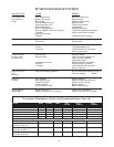
3. By inserting a small screw
driver between the valve
seat (27) and the valve
spring retainer (30), the
valve assembly can be
separated.
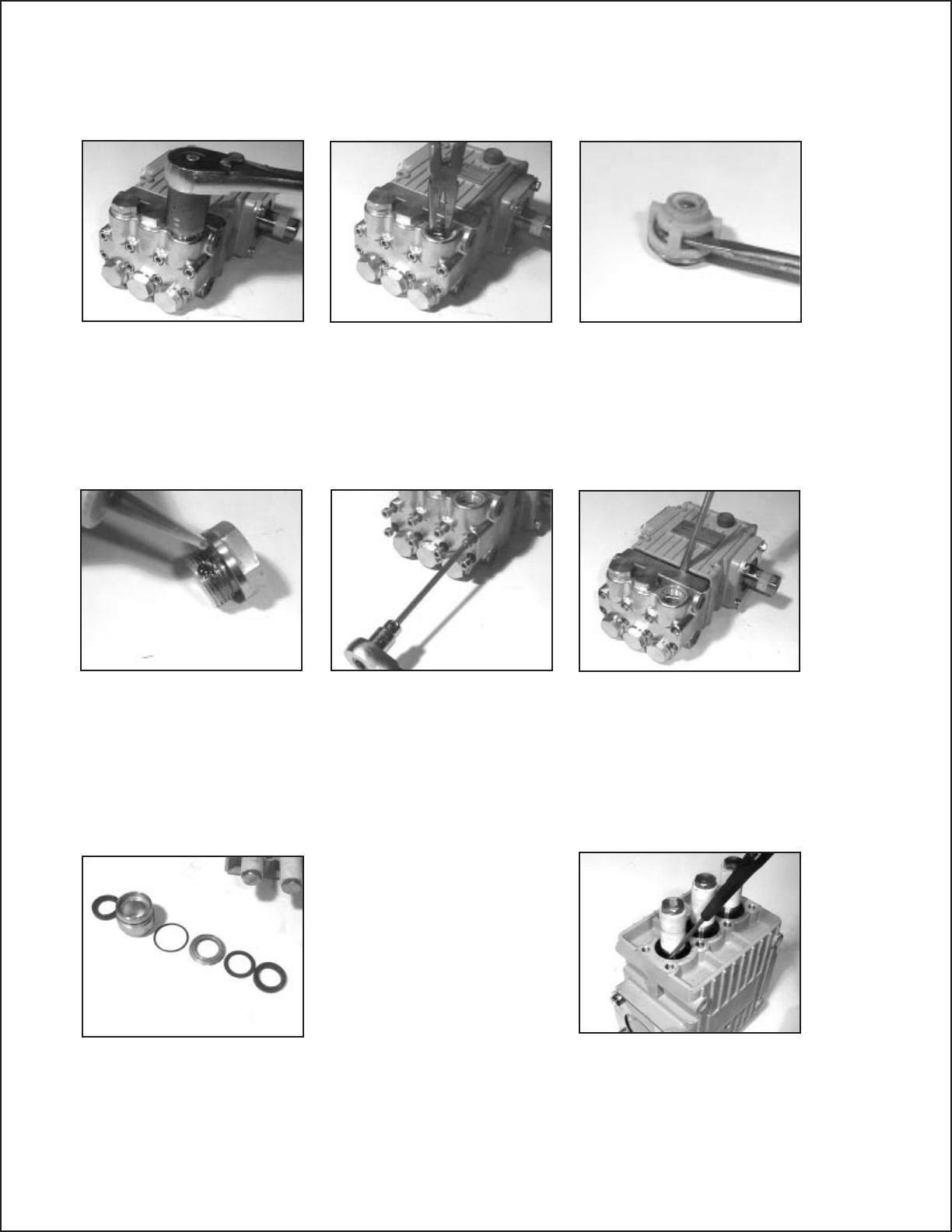
7. Remove the weep return
ring (25), pressure ring
(24), and v-sleeve (23)
from the valve casing (26).
The spacer ring (30A) on
CP230 pumps may remain
inside the valve casing.
Remove the v-sleeve
(23A) from the seal case
(20). Inspect all parts,
including o-ring (21) for
wear and replace as
necessary
8. Check surfaces of plunger
(16). A damaged surface
will cause accelerated
wear on the seals. Depos-
its of any kind must be
carefully removed from
the plunger surface. A
damaged plunger must be
replaced!
9. If the crankcase oil seals
(19) are to be replaced,
they can be removed by
prying loose with a flat
screwdriver. Take care
not to make contact with
the plunger.
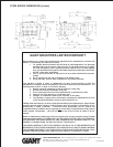
4. Remove the o-ring (31).
Inspect all parts for wear
and replace as necessary.
For pumps manufactured
prior to 5/97, tighten plugs
(32) to 33 ft-lbs. otherwise,
apply one drop of Loctite
243 to the valve plugs (32)
and tighten to 59 ft.-lbs.
5. Next, use a 5mm allen
wrench to remove the 8
socket head cap screws
(34).
6. Carefully slide the valve
casing (26) out over the
plungers.
REPAIR INSTRUCTIONS - CP200 PUMPS