


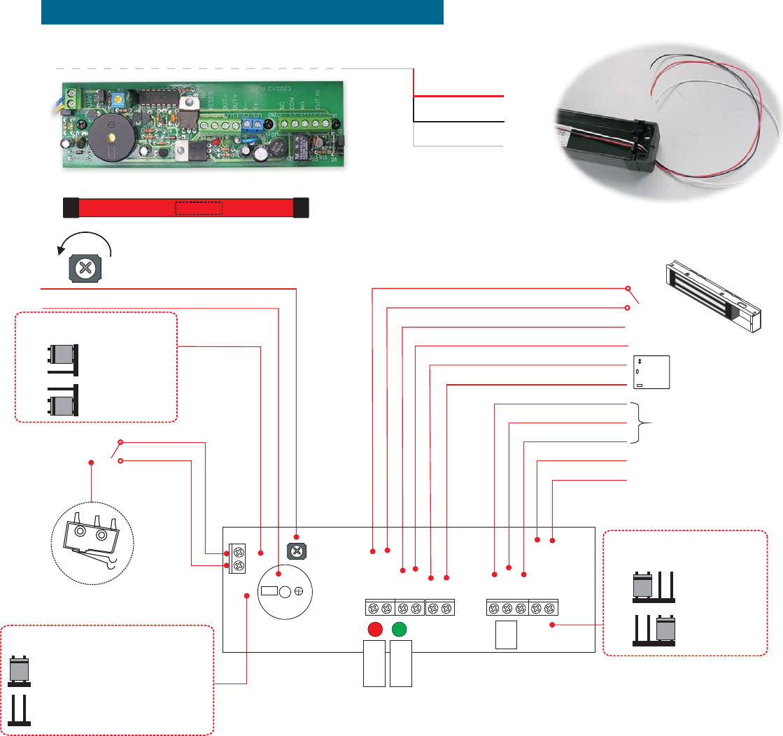
Switch 2 output
(Switch 1 output)
START
Red (N/C)
Black (COM.)
White (N/O)
RESET contact
RESET contact
Adjustable delaytimer (1-30 SECONDS)
95db Sounder
RESET
RESET
N.C.
COM.
N.O.
CUT INPUT
CUT INPUT
out-
out+
RELAY
V-
V+
35 1
Power input 12 Vdc+
Power input 12 Vdc-
Power output 12 Vdc-
Power output 12 Vdc-
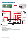
GEM
Electromagnetic lock
(Fail-safe)
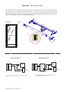
PBA-860TDI control panel wiring diagram
J1 Set contact time for triggering
J2
N.C. / N.O. trigger selectable
Key switch
J3
N.C. / N.O. trigger selectable
for mergency condition
N.O. Rigger
N.C. Rigger
N.O.Rigger
N.C.Rigger
3 seconds constant contacting
(Power)
()Buzzer
Buzzer
signal output
signal input for emergency
OUT +/- (Over pass timer
setting prior to cut out power
0.5 second
Manual Instructions
* P1 , P2 setting for trigger N.O. or N.C. contact and timmer adjustable.
* OUT +/- voltage output eliminated after1-30seconds delay timer set, an over pass timer setting OUT +/- prior to cut out power
instantly when emergency (CUT INPUT) condition.
* P3 setting for trigger N.C. or N.O. contact on emergency condition.
* Buzzer and signal output for termination control purposer, contact rated 3A@12VDC or 1A@125VAC
* RESET for stand by activation.
* Electromagnet lock is fail-safe version, recommend to use UL approved power supply unit for UPS (uninterruption Power Supply)
system integration at any time.
Power supply
CopyrightGianni Industries,Inc.All RightsReserved.
PublishP-MU-PBA860 Ver. D :2007.03.23