


Copyright All Rights Reserved.
P-MU-982-10 Ver. A Publish:2004.05.01 Page: 2/ 4
added to memory. Once all the required tags have been presented, read the Master Tag to
return to the RUN state.
Delete Tags
To remove a tag from the system, that tag must be available or the Tag Simulator must be
used. If these are not available, the system memory must be cleared and all valid tags re-added.
To select this function:
Read the Master Tag twice with a time between reads of less than 2 seconds. →The RED
lamp will light. → Wait for the RED lamp to start flashing.
The Easiprox is now in the DELETE state. In this state every tag that is presented to the
reader will be deleted from the system memory. (Tags can now also be deleted by using the
optional Tag Simulator.) Once the tag or a group of tags have been deleted, read the Master Tag
to return to the RUN state.
Clear Memory
To delete all the tags from the memory including the Master Tag and Strike time, place the unit
in the CLEAR MEMORY state.
Read the Master Tag three times with a time between reads of less than 2 seconds. →
The YELLOW and RED lamps will light. → Wait for the YELLOW and RED lamps to start
flashing.
The Easiprox is now in the CLEAR MEMORY state. Now present any tag except the Master
Tag to the reader and all memory will be cleared. Alternatively, read the Master Tag to abort this
function. Once the memory is cleared the YELLOW and GREEN lamps will flash to indicate that
the memory is empty.
Time Adjust
This function sets the relay operating time for a push-button input and a valid card read.
To select this function:
Read the Master Tag 4 times with a time between reads of less than 2 seconds. → All the
lamps will go off. → Wait for the YELLOW lamp to start flashing.
The Easiprox is now in the TIME ADJUST state and each flash of the YELLOW lamp equates
to 1 second of relay operation time. Once the desired time is reached (max 60 seconds), read
the Master Tag to store the time and return to the Run state. If TOGGLE mode is required
simply allow the YELLOW lamp to flash until it stops automatically (after 61 flashes). The unit
will now be in TOGGLE mode.
INSTALLATION
POWER
Connect 8-12V AC or 10-14V DC to the 12V AC/DC terminals on the controller. The polarity of the
connection is not important.
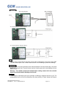
ELECTRIFIED DOOR LOCK
The unit provides a relay output rated at 24 VDC at 3A . The following contacts, that are
isolated from the rest of the board, are provided; normally open (NO) contact, normally closed
(NC) contact and a common (COM). Typical connections to a door strike are shown on the
drawing.