


NOTE
For lightweight garage doors, make sure you have
installed the proper reinforcement (See Check Door
Condition and Thickness on page 5 in manual),
• TheHeaderBracketmustbefastenedto the
mounting plate for the Header Bracket,The
Bracketcanthen be mounted at the propel
location and havesufficient Support.
If adoor spring is in the way placethe Header
Bracketabove the spring, Do Not move the door
spdngi
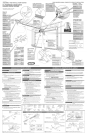
A Before mounting the header bracket, see CHECK
STEP4, in Operation & Maintenance Manual for
mounting instructions, ff needed, attach a 2"x 6"
board across wall studs where you made your
Header Bracket mounting point mark (Figure 8).
Transfer your mark from wall to board.
B Attach Header Bracket to header at your mark
above garage door.
NOTE
R is critical that point where Rail attaches to
Bracket be on centedine of Door.
Mark two Bracket hole mocations.
Drill 2 (5/32") pibt homes.
Attach Header Bracket using 2 (1/4"x 2") Lag
Screws.
DOoisrnadeof mas0nite:lightweightWOod, I
fiberglass,metN,orotherlightweightmaterialsmust
be proper y braced before mount ng door Opener. J
For sectional doors:
A Place Door Bracket on door center line, no lower
than top roller, and mark holes (Figure gh
[3 Attach Door Bracket:
For metal doors, use 3 (1/4" =20x 3/4") Self_
Dri[ming Screws (provided).
For wooden doors, use 3 (1/4" x 2") Lag Screws or
_ (1/4" x 1=!/4") Lag Screws or 3 (1/4" x 2=1/2")
arriage boks (not provided).j
Beforeinstalling, check length of the induded Lag
Screwsvs.the thickness ofyour garagedoor. For doors
thinner than 2", use1ol/4" LagScrews.Checkdoor
condition and thickness.Seepage3 in Operation &
Maintenance Manual
For one-piece doors:
A Position Door Bracket on door's center line, as high
as possible or on top of door.
B Attach Door Bracket:
For metal doors, use 3 (1/4" =20 x 3/4'*) Serf=
DNlling Screws.
For wooden doors, use 3 (1/4" x 2") Lag Screws
or 3 (1/4" x 2")Carriage hefts (not provided).
ATTACH RA|L TO HEADER
[}RACKET
A While supporting the Power Head, place threaded
end of Rail Strap Bolt through Header Bracket hole
(Figure lg).
B Attach (S/16"=18) FDnge Nut to Rail Strap Bolt.
Finger=tighten unti| |ater.
MOUNT'NOPowERHEA
Z UTnO
ounting Bracketsmust befastenedto garaqefram!ng,De Ngt 1
fastento drywall,particleboard,plaster,or orbet suct_rhateriak
. MakesuretherailofyoursupportedPowerHeadisslightlyhigherthan
thehighestpointofdoortravelbyraisingthedoortocheck.Adjustas
needed,
, MaterialsneededformountingOpenerPowerHeadtogaragemay
vary.Readallinstructionscompletely.
. Garageconstructionsdiffer.Extramaterialmaybeneeded,SeeCheck
PowerHeadMountingAreaonpage7inmanual
A RaisePowerHeadandsupport ithigh enoughthatyou can
manuallyraisethegaragedoor fulmyopen,
B Lineup PowerHeadandRailwith center ofgaragedoor.
C KeepingPowerHeadcentered,mountto ceiming:
Atproper height;
a. Forsectieea[ deers, mountpower headataheight
whererail islevelwithfleer orslightly bwer.
- CheckforclearancebetweenRailanddoorasit
opens(Figure11).
b, Foror.e-piecedeers, mount powerheadsothat
there isaminimum dearanceof2"betweenrailand
doorasitopens(Figure11).
D Usingoneofthe preferredmethodsshown(Figure12},mount
PowerHead(Use5/1B'-18x3/4 hexhead BoltsandS/16'q8
FlangeNuts).(Itispossibb to useothermounting methods,The
criticalpoint to rememberisthatthe mountingassemblymust
besolidlyattachedandableto support theweight of thePower
Head.)DONOTATTACHTODRYWALLORSUSPENDEDCEILING.It
must beanchoredto thegarageframework,
ASSEMBLEAND CONNECT
DOOR ARMS
For sectional doors:
A Attach short side of Curved Door Arm to Door
Bracket with Clevis Pin and Cotter Pin (Figure 13).
[3 Attach Straight Door Arm to Carriage with Clevis
Pin and Cotter Pin.
C Attach both Arms together with 2 (3/'8" x 7/8") Hex
Head Bolts and 2 (3/8") Serrated Flange Hex Nuts
so overal[ [ength is as short as possible. Securely
tighten fasteners.
D Adjust height of Emergency Release Cord Knob to
6' above floor:
Pull Cord through Carriage Release Lever until
Knob is 6' from floor.
Tie a new overhand knot in Cord at Carriage
Release Lever.
For one-piece doors:
A Attach Straight Arm to Door Bracket with CmevisPin
and Cotter Pin (Figure 14).
B Attach short side of Curved Arm to Carriage with
Clevis Pin and Cotter Pin.
C Attach both Arms together with 2 (3/8'* x 7/8") Hex
Head goffs and 2 (3/8") Serrated Fbnge Hex Nuts
so overall length is as |ong as possible_ Securemy
tighten fasteners.
D Adjust height of Emergency Release Cord Knob to
6' above floor:
Pull Cord through Carriage Release Lever until
Knob is 6' from floor.
Tie a new overhand knot in Cord at Carriage
Release Lever.
Do Not skip Step D above[
Failureto comply may leave Emergency
ReleaseKnob within reach of Children: ff the
Knob ispulled with ga[age door fully or
partially open, garage door may dose RAPDLY
without wamiDg!
SYSTEM
ELECTRICAL WARNING-
Ensure there isNO power to the Opener before
installing Safe-T-Beam® System wires.!fOpener !s
plugged into outlet, Unplug it Now,
NOTE
The Opener will not dose the door automatically unless
the Safe-T-Beam ® System is installed.
A [nsta[I Safe=T=Beam® Source and Sensor
(Figure1S):
Mark both sides of garage door frame or waHH
6" above floor.
Hold Bracket against door frame or wall Check
if Bracket extends out from wall far enough so
tongue of Bracket is beyond door, tracks, or
any door hardware. Hfnot, Safe=T=Beam®
Mounting Bracket Extensions are avaimabme
from a Genie Factory Authorized Dealer or
through the Accessories Order Form_
- Bmocksof wood, etc. may be substituted for
extensions.
Position top of Mounting Bracket at 6" mark
and fasten with 2 (#10=! 6 x 1=1/4") Phillips Hex
Head Screws per Bracket.
NOTE
Mounting Brackets can be attached to brick walls or
concrete floor using masonry anchors (not included).
B Attach Safe=T-Beam ® Source (Red LED) and Sensor
(Green LED) to Brackets (Figure 1S):
For s[ngle-door garages_
- Determine which side of garage receives
the most direct sunlight, and place Source
(Red LED) on this side whenever possible.
For multipb-door garages see (Figure 16).
Preventing crossed signals is critical
Place Source and Sensor modules on
adjacent doors facing in opposite directions.
[ NOTE
To help prevent interference from the sun, the Safe-T-
Beam ®Sensor (Green LED) may be placed further away
Ifromthe door opening,where it will spendmore time
in the shadows.
Slide the Safe-T-Beam ®Source and Sensor
onto the tongues of the Brackets until they
click into pbce,
Check final height of Lens (Figure 17).
CAUTmON
StapleswhicharetOOtight mayCutorpinchWires.CUt
or pinchedWirescancausetheSafe-T-Beam®System
tostopworking,Wheninsta!lingthe Bulated Staples,
makesureyoufastenthemOn!yastightly asneeded
to holdtheWiresecurely.
C Install Safe-T-Beam ®Wiring: (Figure 18)
Route Wire and hsu[ated Stapmes
(F_gure lg, and 20).
- Securemyfasten Wires with hsuhted
Stapbs as you go. Stapbs should be snug
only.
- Wires between garage wall and Power
Head should be run on top of Rail and
underneath Wire Cmips.
Attach Wires to Safe=ToBeam ®Sensors.
- Spmitand strip Wire ends to be connected
as shown.
- Loosen Terminal Screws.
- insert each Wire under flat plate and
tighten Screw. It does not matter which
Wire, white or striped, goes on which
Terminal,
Attach Wires at Power Head.
- Wires are connected to Terminals #3 and
#4 on Power Head Terminal Block. ff does
not matter which WR'e, white or"striped,
goes on which Terminal
Check the following.
- Ensure that no part of door or its hardware
is in path between Source or Sensor
Lenses.
Ensure that tops of Lenses are between 5"
- 6" above floor. Brackets are flexibme and can
be adjusted sIightmy if needed.
NOTE
®
The Safe-T=Beam alignment check will be performed
following connection to eieEtriEal power. Do Not plug
in yet[
WALL CONTROL[NSTALLA_ON
[_ wAR.m.G
More than one lighted WallCentral per Opener will
causeamaffunEtion.
WALL CONTROL (Figure 21 & 22)
A Finding the mounting location(Figure 22).
Pick a convenient location for mounting wail
control
- Location you choose should be in direct
sight of door.
- h should be at least S'above floor to
prevent small children from operating
door.
- It must be away from any moving parts.
(You should not be able to reach the garage
door while standing at Wall ControL)
[} Wiring (Figure 22):
Run wire from Power Head to Wall Control.
Securemy fasten to ceiling and wall using
insulated staples provided.
SpHit and strip ends of wire.
On Power Head:
- Attach the striped wire to Terminal #1
and white wire to Terminal #2.
On back of Wa[I Control:
- Attach striped wire to Termlna|"B'[and
white wire to Term[naJ "W':
C Mounting:
Fasten wail control to wail with 2 screws.
_ _ #6 x 1=1/4"
Remove protective backing from Entrapment
Warning Label
- Stick bbem on wall near Wall Control
CAUT[O
' Use of any wall Consoles other than the type
Jndudedwillpreventthelightfromworking
hold the Wire snugly.
] A WA RNmN
To reduce the risk Ofe[eEtrical Shock, this equipment
hasagroundedtypeplugthat includesathird
(grounding)pin.Thisplugwi[[onlyfit a groundedtype
outlet, if you do not have a grounded outlet, contact a
qualified electrician to instal[ one. DO NOT aJter the
plug in any way. The door opener must be proper[y
groundedin order to preventpersonalinjuryand
damage to the components.
Connection with grounded plug:
A Checklocal building codes:
Does buimding code require permanent wiring?
ff yes, have an electrician perform
"Connection with permanent wiring" below.
ff no, pmugdoor opener into grounded
outlet.
. Perform Safe=T-Beam ® alignment check below.
Connection with permanent wiri#g
(Instructions for [kensed e_ectrician):
A Remove powerfrom circuit.
B Remove Motor Cover.
Remove 4 screws from Cover and slide down off
of Power Head (Figure 23).
Remove and discard power cord.
Cut power cord inside Power Head.
Remove and throw away power cord, strain
relief and knock uut.
D install suitable entrance bushing and power supply
wire.
Connect permanent wiring to Power Head.
NOTE
There must be at |east 5 inches of black
and white wire inside of Power Head
(between splice and entrance bushing).
- Connect white supply line to white wire.
- Connect black supply line to black wire.
- Connect ground to green wire (ground).
NOTE
Use only UL recognized wire nuts.
Replace Motor Cover.
Slide Cover into place.
Replace and tighten 4 screws.
F Reconnect power to circuit.
Safe-T-Beam e Alignment Check:
After turning electrical power on, if STBsare not
properly aligned, red LED (source) will b_ink
continuously.
B To correct problem--STB mounting brackets are
flexible and may be adjusted slightly to bring the
system into alignment.
When STBsare brought into alignment--red
LED will stop b_inking and stay _it.
FORCE CONTROLS
Rough Setting of Limit Switches
A Setting Close Limit Switch (Pigure 24):
Check that Carriage Assembly is disengaged.
With garage door fully closed, slideClose Limit Switch
toward Carriage ueq it is aligned with
Carriage magnet.
Tighten Set Screw. Do Not over=tighten.
Setting Open Limit Switch:
Manually open garage door to full open
position.
Slide Open Limit Switch toward Carriage unti_
it is aligned with Carriage magnet.
Tighten Set Screw. Do not over=tighten.
Re=engage Carriage Assembly.
Setting Force Controls e_d Final Adjustment
of Limit Switches
m
• Thegarage dooropens rapidly, and Can pause
sedous injury or death.
, Keep the path dear.
. Position the ladder to the side of the Power
Head so it is clear of all moving parts of the
Opener and the door.
- Set the door Opener to use the m!n!mum force
needed to open the door.
Little effort is required to turn the Force
Adjusting Knobs.
ffthe door stops moving while opening or
dosing, adjust the Open Force or Close Force
Controls slightly clockwise (to slightly
increase the force) and retry the step.
The Open Force and Close Force Controls
are tobe set to the mimimum force
necessary to ensure the door smoothly
opens and closes completely.
The garage door wi[[ move slowly the first
time it runs, until the Opener "learns" the
type of door.
Ensure the Carriage Assembly is engaged
and is between the two Limit Switches
before operating the Opener.
A
B
C
D
Pre=set Force Controls to midpoint between
LO and H[ (Figure 25).
Adjust the CHoseLimit Switch:
Press Wall Console to close garage door.
- If door does not dose completely, measure
distance from bottom of door to floor. Move
Limit Switch same amount toward door.
- If door reverses after contacting floor,
move Limit Switch toward Power Head.
- If door reverses before contacting floor,
increase Close force.
Tighten Limit Switch Set Screw. Do not over=
tighten (strip) Limit Switch Set Screw.
Adjust Open Limit Switch:
Press Wall Console to open garage door.
- ffdoor does not open completely, move
Limit Switch toward Power Head.
- ffcarriage is crashing into power head,
move Limit Switch toward door.
Tighten Limit Switch Set Screw. Do not over-
tighten (strip} Limit Switch Set Screw.
Test Door Opener:
Run door up and down a few times using the
Wall Console and observe door travel
Repeat steps above as needed to set Limit
Switch positions.
Adjust Open Force to minimum needed
(Figure 2S):
Place door in dosed position using Wail
Console.
Gently adjust Open Force fully
counterc[ockwBe (minimum force).
Run Opener using VVaHConsole_
Observe that door runs to Open Limit Switch.
- ifnot,adjust Open ForceControl slightly
clockwise, dose garage door,and open it again.
Repeat steps above until garage door runs
smoothHy from Close Limit Switch to Open
Limit Switch.
Adjust C|ose Force to minimum needed
(Figure 2S):
Place door in open position using Wall
Console.
Gently adjust Close Force fully
counterclockwise (minimum force).
Run Opener using Wall Console.
Observe that door runs to Cbse Limit Switch.
- Ifnot,a_ust CloseForceControl slightly
clockwise, open garage door,and close itagain.
Repeat steps above until garage door runs
smoothly from Open Limit Switch to Close
Limit Switch,
SAFE-T-BEA_ ® FUNCTmON
[
Limit Switch and Force Adjustments must be completed
|before checking the contact reverse function F sure 25).
A Open garage door using Wall Console.
Lay a 2" x 4" board flat in center of doorway
(Figure 26).
C CHosedoor using Wa[_Console.
D Check that door stops and reverses within 2 seconds
after it contacts board:
o If door does not reverse, decrease Close Force
untiH door reverses.
, ff door still does not reverse, move Limit
Switch toward door.
E Check Safe=ToBeam® System (STB) operation:
• ff beam is blocked, door will not dose (Figure 27).
NOTE
Thedoormustcontactthe2"x4"boardbeforetheCarriageacti-
vatestheCloseLimit Switch.Ifnot,readjustthe dose LimitSwitch.
Program Transmitter, install Light and Lens
A See Operation & Maintenance Manual.
I NOTA 1
[Parepuertasdesaraede peso[igeras,asegOresedequeha
|instahdo losrefuerzosadecuados(VealasecciBnsobre
[verificaciBnde lacondiciBnyespesordela puertaenlapaginaS)_
_ONTAR EL SOPORTE DE
TRAVESA£O
PRECAUTION
' E[ soportede[travesahodebeasegurarseaB estructurade[garaje.
NoIoasegureaparedesagdetadas,detablesdeaglomerado,yeso,u
otros materMessimilares.
o Puede sernecesadoer.samNarunatabBde2'x6"a b largodela
estructurameteilicadela paredbcalizadaperendmadd travesaho
dela puertaparaquesirvacomeplatademontajedelsoportedel
travesa_o.E[soportepuedeer.toncesmoetarseene[Dgar
adecuadoy tenetrefuerzosuficiente.
Siur.rosettedelapuertainteffiere,coloqueeBoporte de[
travesa_operencimadel resorte.Nomuevaelresortede[apuert&
Siserequiere,ensambleunatabh de2"x 6"(Figure8)cona[menos
dos(cuatroesrecomendaNe)tornillosparamaderayrondanas
planas(noinduidasconelpaquete).
B Ponga el lade derecho de[ abrepuertas hacia arriba, y
sostenga [acaja del motor de manera de evitar el
romper los portal_mparas.
Lasvariaciones de montaje semuestran en iaFigure 8.
Cuaiquiera de esaspuede usarse dependiendo dei espacio.
Sin embargo, escriticoque ei punto donde se ensambia ei
rid a_soporte del travesafro est_ en _aiinea de centre de _a
puerta.
• Marque Insposiciones de los 3agujeros.
• Barrene 3agujeros pibto de 5/32':
• Ensamble el soporte del travesaho usando 3 torni[Ios para
madera de t/4"x 2'.'
_ONTAR EL SOPORTE DE
LA PUERTA
PRECAUT[O
as puertas hechas de masonita, madera ligera, fibra de |
vidno, metal, u otros materia[es ligeros ddSen asegurarse
adecuadamente antes de insta[ar e[ abrepuertas. J
En el Case de Puertas Secci6nadas:
A Co[oquee[soporte de[apuertaen[alineacentral de[apuerta,
procurando quenoquedemasabajode[ rodi[[osuperior,y bs
agujerosguia hechos(Rgwa 9).
[} Acopbr el soporte de Hapuerta:
• Parapuertas met_[icas, user3 torni[[os autorroscantes
(de 1/4"=20x 3/4") (que seproveen).
• Parapuertas de madera, usar 3 pijas (de 1/4"x 2"6
3 pijas (de 1/4"x 1=1/4")(no seproveen).
[
Antes de instalar,verifique b Iongitud de bs tornillos para madera
induidos en el paquete contrad espesor de la puerta de su garaie,
Para puertasm_s ddgadas a 2';use tornillos para madera de -1/4'.
VerifiqueHacondkidn y espesordelapuerta.VeaHapggina3enEl
ManualdeMantenimientoy Operaci6n.
Pare Puertas de ann sole plezas:
A Coloqueelsoportedeb puertaenla[ineacentral deB puerta,
tanalto comeseaposiNeo ensucaseenb partesuperiordeb
puerta.
B EnsamNeel soportedeb puerta:
• Parepuertasdemetal use3torni[[osautoroscarttesde
(1/4"-20 x3/4")(induidos enelpaquete).
, Parapuertasdemadera,use3tornillosparamaderadel/4"x2't
SOPORTE DELTRAVESANO
A EnsambHeeHextreme roscadodellpernodeHacintadd rid eneH
agujerode[soportede[travesaflo(Figure 10).
Coloqueunatuercade reborde(5/16"-18)enelpernode la
cintadelrieLAprietemanualmente
ENSA_4BLELACAJABELMOTOR
[)ELGARAJE
PRECAUTION ]
Lossoporte_de moRtajedeber,asegurarse_ laestructuradel
garaje,Nolosasegureaparedes,detaNasde aglomerado,yeso,u
otros materiaesslmi ares J
insulated Staples
(approximately 30 parts)
Grapesaisbntes (Approx 30inidades)
#6=11/4"
Pan Head Screws
TorniI[os de cabeza
troncocBnica#6 = ]=1/4"
Hardware(red bag)
NOTA
. AsegOresedequeelridde[acaade[motorco[ocadaest_[igeramentem_s
altoquee[puntom_saltode[acarreram_ximadeviaede[apuerta,
mediante[ae[evad6nde[apuertaparaverificado.Ajustecomeseanecesado.
Losmaterialesparae[montajede[acajade[motorde[abrepuertaspueden
variar.Leatodaslasinstrucdonescomp[etamente.
, Lasconstrucdonesdelossaraesvarian.Sepuederequerkmaterialextra.Vea
[ap@ina7parevedficare[_reademontajede[acajade[motoc
A
B
C
Levante[acajadecontrol ysopBrtdasuficientem entealto de
maneraquepuedalevantarmanualmente lapuerta delgaraje
abri_ndolatotalmente.
Alineelacajadecontrol y elrid con elcentrede b puerta.
Manteniendocentradalacajadecontrol,monte alcielo raso:
A laaltura cotrecta:
a. En_aspuertasensecciones,e[rid debeestara
nivd con elpisooligeramentedebajo del nNeL
(Figura 11).
b. En_aspuertasdeunasoHapieza,eHrid nodebe
interferirper unas2pulgadas.(Figure11).
Usandounode losm_todospreferidosque semuestra,
(Figure12),monteb cajadecontrol.(Esposibb usarotro
re@odedemontaje.E[punto crfticoquerecordaresqueel
conjunto dd montaje debeestersBlidamenteacopBdoyser
capazdesoportare[pesode b cajadecontroL)NOACOPLEA
UNAPAREDDETABLAROCAOAUNCIELORASOSUSPENDDO.
Debeestarandado alentramadodeb estructuradelgaraje.
_ONTAR Y CONECTAR
LOS BRAZOE DE LA PUERTA
Pare puertas secdo_es
A AcopBr el lade torte dd braze curvado de D puerta a_
soporte de b puerta con el pasador de horquilb y b
chaveta de dos pates (Figure 13).
[} Ensambbelbrazerectode_apuertaalensamNedd eorredizo
magn@ico.
C EnsamNeambosbrazesjuntos usando2pernosdecabeza
hexagonal(3/8"x 7/8")y2tuercasde rebordehexagonal(3/8'!
demaneraqueb Iongitudtotal quedetan cortacomesea
posible.Apriete todos lossujetadoresmanualmente_
D AjusteHaaHturadeHamanijade HacuerdadeHiberaci6nde
emergenciaa6' sobreel nivd dd piso:
. ColoquelacuerdaatravSsdd ensambledd corredizo
magn@co hastequelamanijaquedea6 'dd piso.
. Hagaun nuevomedio nudeenlacuerdaen lalevadel
ensambledd corredizomagn@co.
Pare p_ertasde ann solepieza:
A Ensembled brazerectoa[soportede[apuertausandoe[
pasadorde horquilb y ladavija ben@@(Figure14).
Acop[ar el [ado corto del braze curvado de [a puerta al
corredizo con el pasador de horquiIB yla chaveta de
dos pates.
C EnsamNeambosbrazesjuntos usando2pernosdecabeza
hexagonal(3/8"x 7/8")y2tuercasde rebordehexagonal(3/8")
demaneraquela Iongitud total quedetan [argacome sea
posible Apriete lossujetadoresmanualmente.
D Ajustelaalturadelamaniiade lacuerdadeliberaciBnde
emergenciaa6' sobreel niveldd piso:
" CoHoqueHacuerdaatra%sdd ensambHedd corredizo
magn@co hastaque[amanijaquede a6 'dd piso.
. Hagaun nuevomedio nudeenlacuerdaen b levadd
ensamNedd corredizomash@ice.
_ede @jar [
[_os.Si b [
INSTALEELSISTEMA
SAFE-T-BEAM®
EHabrepuertas no cerrarg [apuerta autom_ticamente a
menos que el sistema Safe=T=Beam®est_ instabdo.
InstaBd6nde Bfuentey e[sensorde[Safe-T-Beam®(Figure 15):
• Pongaunamarcaenambos_adosdd marcodepuerta del
garajeoenlapareda6"perencimadel piSOa
° Sostengael soportecontra elmarcodelapuertaola pared.
VerifiquesielsoportesobresaledelaparedIosuficiente
come paraquelaespigaseextiendahacialapuerta,sus
guiasdedeslizamientoo algOnotro componente.
- Encasequeno,existendisponiblesextensionesde[
soportede montajedel Safe-T-Beam®con undistribuidor
autorizadodef_bRcaGenieo atray,s dd formatede
pedido deaccesoriOSa
- Losbbques demadera etc puedensersubstituidosper
extensiones.
o Co[oquelapartesuperiordd soportedemontaieen B
marcahecha 6"y asegurecon2tornillos Phillipsdecruz
cabezahexagonalpersoporte dd( #10-16x1-I/4")
i NOTA ]
Lossoportes de montaje se pueden instabr en paredes de
ladrilb o de concrete usando andas para mamposteria (no
induidas en el paquete).
B EnsambHeb fuente(diode emisorrojo)ydd sensor(diode
emisorverde)del Safe-T-Beam®alossoportes(Figura 15):
o Paragarajesdeunasob puerta:
- Determinequ_bdo dd garajerecibeb mayorcantidadde
bz dd soldirecta,ycoloqueel foco( diodeemisorrojo)de
lacajadel motoren_stdadosiemprequeseaposiNe.
o ParegarajesdepuertasmO[tip[esvea[a(F[gwa16):
- Elprevenirlassehalescruzadasescritico.
- Cdoque losmBdulosdeb fuenteyd sensorenpuertas
anexasapuntando haciadirecdones opuestasentresL
NOTA
Paraayudar a prevenir interferencia con el sol,elsensor dd
Safe=T-Beam®(diode emisor verde) puede colocarse lejos
del vane de la puerta, ee un Dgar ee donde est_ D mayor
parte dd tiempo a B sombre.
o Des[iceb fuerttedelmotor y d sensordd sistemaSafe-T-
Beam®enlasespigasdelossoporteshastaqueatorenensu
[ugar.
o Verifiqueb alturafinal debs bntes delsensor(Figure 17).
C InstalaciondeSafe-T-BeameWiring(Figure 1B):
. Enrutee[cablecon [asgrapasais[antes(Figwa 19yFigure 20):
- Sujetedemaneraseguraloscablescon grapesaisbntes
conformelosvayaenrutando.Lasgrapasdebenabrazar
sdamente bs cables.
- Loscablesquevanentrela pareddd garajeyb cajadd
motor deben guiarsesobre b parte superiordd rid yper
debajodelossujetadoresdeloscables.
• EnsamNeloscablesalossensoresdd Safe-T-Beam®
- Separey palebsextremesfinalesdeloscablesparaconectar
loscome semuestra.
- Aflojelostornillos delasterminJes.
- Insertecadacableper debajode lapbca pinnay aprietee[
torni[Io.Noimporta cualcable,blancoo rayado,vaencual
terminal.
, EnsamNeloscanes ala cajadepotencia.
- Loscablesseconectan alasterminales#2y#3dd
Noque determinales delacajadd motor,Noimporta
cualcable,bBnco orayado,vaencualterminal
, Verifique[osiguiente:
- Que ningunapartedeB puertao suscomponentes
interfiereentre lafuentey Dslentesdd sensor.
, Aseg@eseque Bpare superiordeBslentesest_
entre5y6"per encimadd piso.Lossoportesson
flexiNesypuedenajustarseligeramentesiesnecesano.
NOCONECTETODAVlA!
[NSTALAC_0NDELACONTROL
DEPARE#
ZL ADVERTENC A
Verifiquequeno hayaenergiael@tricahaciael abrepuertasantes
deinsta[arloscanes de[aconsoledepared. J
NOTA
M_s de un control de pared iDminado per e_abre puertas
)rovocar5 un maffuncionamiento_
CONTROL DE PARED (Figura 21 y 22)
A Encontrar el [ugar montaje (Figura 22):
EscogerunDgar conveniente paraelmontaje dd control
depared.
Elbgarqueescojadebeestarenb linenvisualdeb
puerta.
DebeestarperIomenosa5piesarribadelpisopara
impedirquelosnihospequehoshaganfuncionar[apuerta.
Debeestarabjadodelaspartesm6v@s(Usteddebeset
capazdeakanzarBpuertaestandoene[controldepared.)
B Cab[eado (Figure22):
Instabr el canede b cajade controlalcontroldepared.
Apretarde maneraseguraaHcido rasousandoHasgrapes
aisladasque seproveen.
Partuypelarlosextremesdelcable.
Enla cajade control:
- Acoplare[cablepdado altermmal #I y
e[cane blaneoalterminal #2
Atr_sdelcontrol de pared:
- Acoplare[cablepdado alterm!nal '3",y
e[cane blanco alterminal "W".
C Montaje:
Sujetare[control de paredalaparedcon
2torni,,os _}_@ #6x1=1/4"
Quitar e[forro interne protector de[a
etiqueta deadvertencia de"atrapamiento".(Figura 23).
- PegarB etiqueta en lapared,cercadd
control depared
P AuTm.
*Elusode cua[quierconsolade pareddiferentea[tipo
ieduido en este paquete evitar_ que [a Dz trabaje
adecuadamente y podr[a causar que la puerta Opere sin
que se haya accionado intencionalmente.
oLoscable en cordo u opnmidos pueden causar que [a
console de pared no fuhcione. Siempre que use grapes
aisBntes asegOrese de co[ocadas tan distantes come se
requiera pare mantener os cab esjuntos,
_L
CONECTAR LA POTENCmA
C[A
, Conelfindereducirelriesgodechequeel_ctBco,ekeequipotiene
unenchufetipotierraquecuentaconunatercerterminal.Esta
conexiBnseadaptar_solamenteaunatomedecorrientequecuente
_tipodeer.tradaadiciona.Sie enchufer.oentraen atoma
contacteunelectricistacertificado ueleinstalela
siemprequesetrabajeconlasinstalacionesel@tr[caL
CONEXI&N CON _OLmOTAPON
Co_ Enchufe Macho CuR Coeexi6_ A Tierrao
A
Enchufar e_operador de la puerta.
Vea Advertencia de arriba.
- Enchufar e_operador de la puerta en un tom
acorriente con clavija a tierra.
Realice cheque de alineaci6n de STB.
CONEX[ON CON EL ALA_BRADO PER_ANENTE
{|nstruc¢iones pare ememectridsta)
A Desconecte b a_imentad6n de[ drcuito deNvado.
B Quitar B tapa del motor.
Quitar 4 tornilbs de b tapa y resbabr abajo fuera
de b caja de control (Figure 23).
C Quite y deseche el cord6n de alimentaci6n existente.
Corte cuerda de poder dentro de caja de control
Quite y tire e_poder cuerda, e_alivio del esfuerzo
y knockout.
NOTA
Elcableado permanente adentro de la caja de
control debe 6" minimo.
InstaHeunaentradade manguito adecuada.
ConecteeHcabHeadopermanenteadentrodeHa
cajadecontrol.
- Conectee[cable dealimentaciBnblancoal
aBmbreblanco.
- Conecteelcable dealimentaciBnnegroal
alambrenegro.
- Conectee[abmbre detierraalabmbre verde(TIERRA).
NOTA
Elcableado permanente adentro de la caja de
CONtroldebe 6" minimo.
E Vudvaa instaBr[atapade[acajadecontrd.
DesHice[atapa, recto.
Apriete loscuatro(4)tomilbs.
F ReconectelaalimentaciBnel_ctricaalcircuito derivado.
Verificar _aa[i_eadB_de[Safe-T-Beam®:
A Despu_sdeconectarHaa[imentaci6nd_ctrica,s[d
STBnoest_alineadocorrectamente,e[DIODO
LUMNSCENTErojo (fuente)parpadear_continuamente.
B Paracorregire[proNema- bscartdas sonf[exiNesyse
pueden ajustarligeramenteparaponere[sistemaenalineaciBn.
Cuandoe[STBest_alineadoelDIODOLUMINBCENTE
rojodejar_de parpadeary permanecer_encendido.
m
FUAR LOS CONTROLE$ DE
LOS [NTERRUPTORES Y LA FUERZA PosmcmoN DE AJUSTE
APRO×m_AOO DE LOS _NTERRUPTORESLm_|TADORES.
Aj_steaproximadodelos intetrruptorsdem_mitBs
A PosiciBndeajusteaproximadode[interrupter[irrfitadordeCERRAR
(Figure24),
' Verificarqueconjuntodelcorredizoest_desenganchad.
Conlapuertade[garajetotalmentecerrada,resba[are[interrupter
[imitadordeCERRARhadae[corredizohastequee[mismoest_
a[ineadocone[magnetode[corredize
B Austede[interrupterdelimitepareapertura:
o Abraapuertadegarajemanuamentehastaque egueaaposiciBn
comp[etamenteabierta.
, Deslizere[intrruptorlimitadordeABR[Rhadae[corredizohasteque
e[mismoest_a[ineadoconelmagnetode[corrediz&
• Aprieteeltorni[[odefi aciBnde[IfmiteNo[osobreapriete.
Vue[vaaconectarloscontro[esdeajustedefuerzade[ensamb[ede[
corredizomagn@coylosinterruptoresdeajustedelos[{mites.
LosCoRtremesPo_ieRtesdemaFuerzay UmiteQ_eAjustan
m
ADVERTENC[A
o La puerta del garaje se abre r_pidamente, y puede
. causar dahos severos o la muerte.
Despeje e[ _rea,
Co[oque la escalera aun costado de [a caja de[ motor"
con e[ fin de alejarla de todas [as partes en
, movimiento delabrepuertas y de la puerta.
Ajuste al abrepuertas de rnanera que use e[ minirno de
fufuerza pare abdrla.
A Pre-fijarloscontro[esdefuerzaene[puntomedioentreBAJO(LO)y
ALTO(HI)(Figure25),
B Ajustede[interrupterde[[[mitedederre:
, Presionebconsdadeparedparecerrarhpuertadelsarae.
- Silapuertanoderracompletamente,mida[adistanciadesdela
parteinferiorde[apuertahastaelpBo.Muevae[interrupterde
[Hmitelamismadistandahacialapuerta.
- Si[apuertaseregresadespu_sdeestab[ecercontactocone[piso,
muevae[interrupterde[[mitehada[acajade[motet
- Si[apuertaseregresaantesdeestab[ecercontactocone[piso,
klcremente[afuerzadecierre.
o Aprieteeltorni[10defijadBndelinterrupterde[[imiteNo[0sobreapriete
C Ajustedelinterrupterde/limitedeapertura:
o Presione[aconsoladeparedparaabrir[apuertade[garae
- 5i[apuertanoseabrecomp[etamente,muevae[interrupterde
[imitehacialacajadelmotor.
- Si[apuertaabrecomp[etamente,petee[motorcontinOa
trabaando,muevae[interrupterde[imitehada[apuerta.
o Aprietee torni odefijaciBnde imite.Noosobreapdete.
Serequiempocoesfuerzoparegirar[asperi[lasdeajustedefuerza.
Encasedeque[apuertasedejedemovermientrasest_abriendoe
cerrando,auBeloscontro[esdefuerzadeaperturaofuerzadederre
ligeramentegirandolaperi[[aene[sentidodelasmaned[[asdelrelo(para
incrementar[igeramentelafuerza)yvue[vaaliniciode_stepunto.
Loscontro[esaefuerzadeapertureyfuerzadederre@benajustarsea[as
necesidadesminimasdefuerzacone[findegarantizarque[apuertaabrey
cierracomp[etaysuavemente
Lapuertade[garaesemover_[entamente[aprimeravezque@ere,hasta
quee[abrepuertas'programe"e[ripedepuertaqueest_acdonando.
AsegOresequee[ensam_o[ede[corredizomagn@coest_enganchadoy se
encuentraenmediodelosdosinterruptores8e[[miteantes8eoperare[
abrepuertas
f
A
B
C
D
NOTA
Pareprotegersunuevainversion,suPOWERMAXest5equipado
con unrolei detiempo yconun contadordecidos,[oscua[es
trabajan untosparaprevenircuakNier dahogeneradoper
taler a loscircuitosel_ctricosdebido aun excesodecidos en
unperiododetiempo muytorte. Sisuabrepuertas
repentinamentesedetienecomerespuestaauncomandodela
consda depared- NODESCONECTELA UN[DAD-
simplemerlteespere10minutes hastaquee_relo detiempo /
contador decidosreinicienuevamente.
LadesconexiBnde_aunidadevitaqueel rebj detiempo /
contador decidossevueha aprogramac
Pruebade[abrepuertas: . , ,
, Accione[apuertaparequeabrayderreunascuantasvecesusando[a
consoledeparedyobservebcarrerade[apuerta.. ....
, _epltalospasosarnDamenclona_osseqOnserequleracone[rmoe
ajusta[[asposicionesdelinterrupterde][mite.
ustedelaruerzaaeaperturaalm[nimonecesario(Figura25}:
Co[oque[apuertaenposkbndecerradausande[aconso[adepaled.
Suavementeajuste[afuerzadeaperturagirandocompletamen_e_a
peril[aensentldocontrarioalasmanedl[asde[relojfuerzaminima.
Accioneelab[epuertasusandolaconsoladepared.
Observequelapuertaseaccionaoeacuerdoalospar_metros
estab[edoosparqe[interrupterde[[[mitedeapertura. , ,,
- SinoajusteelcontroldefuerzadeaperturaqirandoRperil[a
[geramenteene[sentdodelasmanec[[asde[re[oj,derre[a
R puertade[garaje,y_bra[anuevamente_ , ....
epdalospesosantenoresnastaquelapuertadegaraprunaone
suavementedes@e[interruptoroe[[imitedecierrehastae[
interrupterde[[imitedeaperture.
ustelatuerzadecJerreaimmJmonecesario.(Figura25):
Coloque[apuertaen[aposidBnabiertausan[Jolacons@depard,
Suavemen!eajuste[afu?rzadecierregirandolaperi[[aene[sentido
contradooe[asmaneci,asuelreloj(fuerzaminima).
Accionee[ab,repuertasusando[acons@d,epareu.
ObservequeRpuertaseacdonadeacuerdoalospar_metros
estab[eddosparae[interrupterde[[[mitedederre
- Sinoaustee[controldefuerzadecierregirando[aperi[[a
geramenteene sentdode[asmaned[[asde[ e[oj,ce e apueta
nuevamente.
Repitalospesosantedoreshastaq.u.elapue[tadelgarajefuncigne
suavementedes@e[interruptordellimitedeaperturahastael
interrupterde[I/mitedecierre.
VER_FmQUELAFUNOON DE
REVERSAPORCONTACT{:)
Abra[apuerta de[garajeusando[aconso[ade pared.
C0[0queunatablade 2"x 4"pinnaenel centrede[clarede[apuerta.
Cierre[apuerta usando[aconsolede pared.
Verifiqueque[apuerta sedetieney regresa2segundosdespu_s
deque Nzo contactocon latabla.
o Si[apuerta no regresa,disminuya [afuerzadecierre hasta
que[apuerta regrese
• Siaunasi[apuerta no regresa,muevae[ interrupter de
hmite hacialapuerta.
Vedfique[aoperadBnde[sistemaSafe-ToBeame :
° Sie[ hazde [uz est_b[oqueado,[apuerta no.(Figura 27),
NOTA
Lapuerta debe tocar Hatab[a de 2" x 4"antes que el
corredizo active el interrupter de limite de derre. Si no,
reajuste e[ interrupter de _imite de cierre.
ElPasoFinal
El tra_smisorde[ programa, i_sta[a [as [uzes y el lento.
Vea El Manual de Mantenimiento y Operaci6n.
CenterLineaf doer CenterLiceofdoor
La[Rleacentraldepuerta Lalineacentraldepuerta
',
o0a0,dir.0tl;- __!
intoHeader
Monte
directamente.:S2 _g:-:_ _,\>ZLe-:cJL
enelPar_ntesis":-- --- "__' ._:::e:_. derBracket
depared _____ " .::_= oard
Tableadicionaldeapoyo
Figure 8 Attach Header Bracket
Figure 8 Conecte e[ par_ntesis de pared
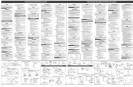
SECTmONAL DOORS ONE-PmECE DOORS
LASPUERTASDE SECC[ONADAS LAS PUERTASDE UNO PEDAZO
CenterL_neaf doer
La[[neacentraldepuerta
Ceeter L_neafdeor
La[ineacentra[depuerta
Figure 9 AttachDoorBracket
Figure 9 ConecteParBntesisde Puerta
Rei[ Strap
Lacorrea de
la baranda
Elpar6ntesis de
encabezamiente
Figure 10 AttachRailStrapto HeaderBracket
Figure 10 Conectebarandacorreaa[par_ntesisde[encabezamiento
SECTIONALDOOR/ Puerta Seccional
CHECKEORCLEARANCE/ VeBfiqueparae_espacio[ibre.
H SLIGHTLYBELOW
Figure 11 Adjust the power head height
Figura 11 Ajuste [aa[tura de cabeza de poder
ONE=PiECEDOOR/ Puerta de una p[eza
MNMU/I OF2"/E[ minimo de 2"
Mounting Straps
Las xorreas que montan
UNFiNiSHED CEiLiNGS
supportbeardaddedformo.gerspa_s
Sostengalatabla agregadapare
espaciosrn_slargos
Perforated Aegme[ren/not in_muded)
Elhierro perforado del angulo
(no induy6)
F|N|SHED CE|L|NG$
Locateceiling joists
ortrusses usinga stud
finder or similardevice.
Attach angle iron
(net included) te
joists or trusses
through finish material
using LagScrews
LOS TECHOS TERM_NADOS
Locabceviguetasde techo o
braguerosque utilizana un
descubridor de semenralo
disposaivo semejante.
Acople un perEIdehierro
_ngulo (no se incluyeen
redes losmode[os)alas
viguetas atrav#sdel mateRa[
acabado usando[aspijas(30).
Figure 12 Mounting methods for open beam and finished ceilings
Figura 12 LosMBtodosque montan para el rayoabierto y terminaron techos
®???
5/!6=18 x 3/4"
Hex Head Bolts
La cabeza hexagonal
cierra de 5/16"=18 x 3/4"
5/16=18 x 3/4"
Hex Serrated FHangeNuts
5/16"=18 Las nueces serradas
hexagona_es de reborde
Header 1/4"x 2" Door Bracket
Bracket Lag Screws
E[parantesis de Lademora encrosca E[par_ntesis de puerta
encapezamiento de 1/4"x 2"
1/4"=20 x 3/4"
Self=Drilling Screws
Los torni[[os que auto
ta_a@ando de t/4"-20 x 3/4"
Safe-T-Beam ®
(STB) Brackets
@
Supportes de_ Safe-T_Seam
As short aspoaaibme
Tan brevemente come /*_,
sea )osibHe_m, qR3k-_)
It_1 /_ "'L _StraightDoorArm
,.-" _/' _'(g_h Elbrazo rectode
(3_z ":_' lapuerta
Curved Door Arm
ElbrazecurvodeHapuerta
Figure13 Assemble Arms (SECTIONAL)
Figure13 Arme armamentos (local) de puerta
Aaioegaa poasibie
Tanlargo como seaposible
El braze curve de lapuerta
\ 5@lraight Door Arm
El braze recto b puerta
Figure 14 Assemble Arms (ONE=P_ECE)
Figure 14 Arme armamentos (uno pedazo) de puerta
®
Safe-T-Beam Sensor
Green LED @
ElSensor (Verde LED)
Safe-T=Reem ®Sourceaf_'_
Red LED
La Fuente (Roio LED)
Figure 1S install Safe=T=Beams ®
Figure 15 [nsta[e Safe-T-Beams ®
_ lide onto
tongue of
Bracket until
it dicks into
place
Desliceen lengua
de par_ntesis hasta
que haga dic en
el lugar __
Topof
// / I":: [ B:racket 6"
.above
' _ (47_ I floor
,_ _ ." _ La alma de
._ , H .'[' parBntesis-6"
i_AI]l'i'-L enc,ma de piso
IIIlfi_!t#_ljI,LLL_
#10=16x 1V4"
Phillips Hex Head Screws
Torni_[o Phillips de cabeza 3/8" Hex Serrated
hexagonal #10-16 x 1-1/4" Flange Nuts
Tuercas de reborde serradas
hexagona_es de 3/8"
Garaje con u_a puerta Garaje con dos puerra
Gara N con tres puerta
Figurer5 Source!sensor Locations
Figure16 Locaci6n de Fuente/Sensor
Top edge of Lens
5" =6" above fbor
Lacima de
par_ntesis =5"-6"
endma de piso
Figure 17 Final Check Safe-T-Beams ®
Figura 17 El cheque final de Safe=T=Beams ®
3/8" x 7/8" _. Cotter Pins
Hex Head Bobs _ ChavetadePernos de cabeza dos pates
hexagona_ de 3/8"x 7/8"
Clevis Pins
Pasadores de horqui[[a
aHambra _-_
..... Aprox. [ H
A r x _< Peb_prox
"_ , i ,/J//Rrip
Wire /// approx.
1 2'"
@ j
Figure 18 Wire the Safe-T-Beam ®System
Figure 22 Wail Control WMng
Figure 22 A[ambrado de Control
Security Vacation Lock Switch
TerminalAttachment at PowerHead
LasRjaciBnesterminales encabezadepoder
Mbw sDck/Permita r_ojo
White Wire to
Termioam2
E"a[ambreb,anco l\\\/11
a,oterm,n. _2%
Etriped Wire %,
toTermina[ 1 _'_j
Elalambre pdad t _
a[aterminal 1
Termieal Attachmeetat Wall Control
Lasfijaci6nes termina[es en [a Central de Pared
TERMINALS
Striped Wire t<_
Te_mina_"B"
Elal ambr e
pelado
terminal "B"
White Wire to
Terminei "W"
Elal ambre
blanco
a [a
terminal"W"
Force
Contro[e
La Fuerza Contro[a
Figure 25 Making Force Adjustments
F_gura 25 Los ajustes de _aFuerza
E_transmiser de[ programa,insta[a _as[oaesyel lento.
Veaa Du@o's/Manua[de Conservaci6npagiea 11.
Knockout pmug/Tap6nmaraviRoso el_ctrico
Cut w_res here.
Elcorte
®
Figure 18 A[ambre el Safe=T-Beam Sistema
Wire cmips/Ela[ambresujeta
!
F
Figure 19 Wiring Method A
Figure lg E[re@ado que a[ambre A
mnsalatedStaples
Termieai attachments
at Safe-T_Beam®
Lasfijacidnes terminales
en SafeoT-Beame
Wire C[ipe Ela[ambre sujeta
@
Figure21 ConsoB de Pared............... o............... Bot6n de pared.
insulatedStaRlet/
Losgrapesaisladas
Te_miea_attachments
at PawerHead
Lasfijacidnes terminales en
cabeza de poder
Figure 20 Wiring Method B
Figure 20 E[m_tado que a[ambre B
Aliewsleekfor
_djustmeRt
Rojopare
elajuste
Terminal attachments
at SafeoT-Beame
Lasfijaddnes termina[es
en Safe-T-Beame
alambra aqui.
Figure 23
Remove screws
Figure 23 _ I
Quita bs TorniHos _,
Screw
Tornillo
Open Limit Switch
(deer felly open)
E[Interrupter
abierto dd I[mite
(puerta abre
completament)
Elcoche (salt6)
ClosedLimit Switch
(door fury dosed) _[_[ ....
EHInterruptor cerrar
de[ [[mite (puerta cerrd
comp_etamente)
Figure24 Settin 9 Limit Switches
Figura 24 El L{mite poniente cambia
2" x 4" board
[aid flat
2"x 4"table co[oc6 [a p[anicie
Figure 26 Checking Contact Reverse
Figure 26 Verificar b Fuerza Inverse
Figure 27 Biock Safe=T=Beame
Figure 27 BHoquee e[ Safe-T-Beam ®