Size selected should result in frictional line loss of 5 psi/100 ft (1.1 kPa/M) or
less for suction lines and 10 psi/100 ft (2.3 kPa/M) or less for discharge lines.
A larger pipe size will reduce the frictional line loss.
W
ARNING: THE PUMP MUST NOT RUN WITH A CLOSED DISCHARGE OR
IRREVERSIBLE DAMAGE TO THE WETTED INTERNAL PARTS
OF THE PUMP WILL RESULT!
3.3.3 Pump Piping Connections
The standard inlet and discharge connections for a Series 500 pump is a
3/4-inch NPT female pipe thread, and for Series 1000 and 1800 pumps is
1-1/4-inch Victaulic couplings/clamped unions with gasket. Victaulic cou-
plings are available worldwide. Contact the factory or your local industrial
piping wholesaler.
3.3.4 Inlet Line Screen/Filter
This is a precision multi-stage pump with close tolerances to provide maxi-
mum efficiency. It is good practice to install a large area 30-mesh or finer
screen, or a cartridge filter in the pump inlet line to collect any foreign objects
or large particles. Size the screen or filter so as to induce a minimal pressure
drop.
W
ARNING: THE PUMP MUST NOT BE OPERATED WITH RESTRICTED SUC-
TION LINE (INLET) FLOW.
Positive gauge pressure must be maintained at the pump inlet (downstream
from the screen or filter). A clogged screen or filter will result in a greater
pressure drop than a clean screen or filter. To prevent possible pump dam-
age from low inlet pressure, a low-pressure alarm or shut-off switch should be
located between the screen or filter and the pump. A low-flow shut-off switch
should also be located in the same area.
3.3.5 Discharge Screen (Strainer)
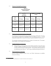
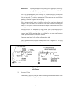
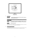
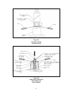
A 30-mesh screen (available as an accessory for 500, 1000 and 1800 Series
pumps) located in the discharge piping will protect your process fluid should
the pump be damaged. The installation of the screen is shown in
Figure 3.2 (Installation of Discharge Screen).
7


