


Catalog Number: RSP12
RSP12
RED
BLACK
WHITE
RED
BLACK
WHITE
RED
BLACK
WHITE
RED
BLACK
WHITE
RED
BLACK
WHITE
RED
BLACK
WHITE
RED
BLACK
WHITE
RED
BLACK
WHITE
RED
BLACK
WHITE
RED
BLACK
WHITE
RED
BLACK
WHITE
RED
BLACK
WHITE
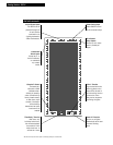
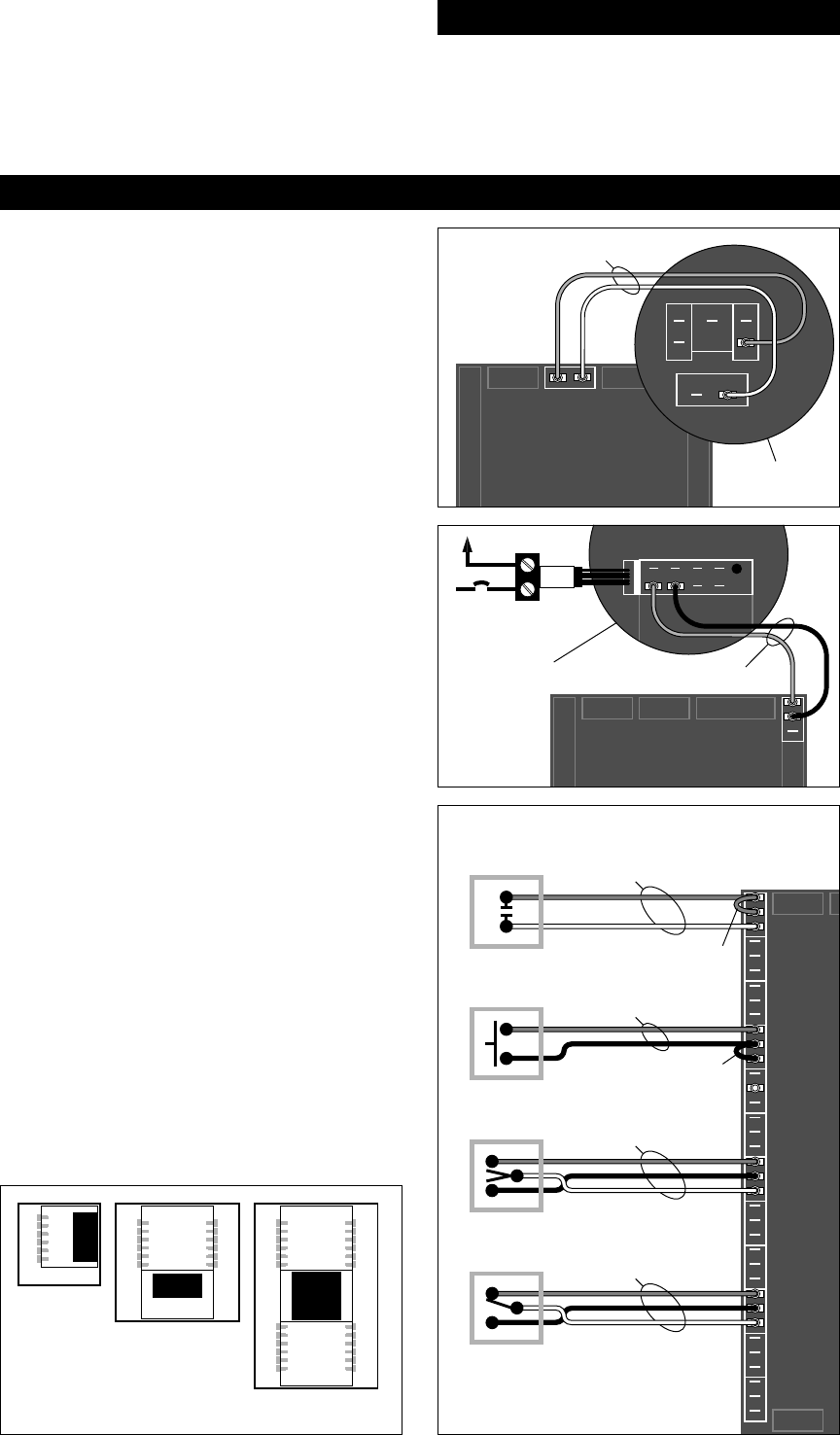
MAINTAINED
ISOLATED
CONTACT
2-WIRE
MOMENTARY
PUSH BUTTON
STANDARD
3-WIRE
MOMENTARY
STANDARD
3-WIRE
MAINTAINED
20/2 AWG 1000 FT. MAX.
20/2 AWG 1000 FT. MAX.
20/3 AWG 1000 FT. MAX.
20/3 AWG 1000 FT. MAX.
JUMP RED TO BLACK
JUMP BLACK TO WHITE
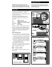
12-RELAY
LIGHTING
AUTOMATION
PANEL
24-RELAY LIGHTING
AUTOMATION PANEL
48-RELAY LIGHTING
AUTOMATION PANEL
RSP12
RED
BLACK
BLUE
ON TLC PANEL
MOTHERBOARD
YELLOWRED BLACK WHITE
1
RRxP RELAY
LOAD
CIRCUIT
20/2 AWG
24VRECT ACC
BLUE WHITE
24V
RECT
BLUE
PILOT
COMMON
YELLOW
24VAC COM
2
4V
RECT
BLUE
ON TLC PANEL
MOTHERBOARD
18/2 AWG
RSP12
INSTALLATION
CAUTION: The power supply must be OFF when
inserting or removing components. These instructions
assume the panel has a standard cover which exposes
both line-voltage and low-voltage sections. The line-
voltage sections must be covered to avoid exposure to
live high-voltage wiring.
There are two recommended ways to install the RSP12
Remote Control Smart Sweeper — in a Lighting
Automation Panel (LAP) or in an Accessory Cabinet near
a Lighting Automation Panel
Installation in a Lighting Automation Panel
A complete LAP assembly includes the following TLC
components:
Tub RTUB12, -24 or -48
Cover RCOV12xx, -24xxx or -48xxx
Interior RINTER0012RC, -0024RC or -0048RC*
Power Supply RPWRxxx
Relays RR7P or RR9P
* RINTER0012RC and -0024RC accept one RSP12, RINTER0048RC accepts one or two
Details for assembling a complete Lighting Automation
Panel are outlined separately in the RINTER installation
instructions. Once the panel is assembled and relays are
connected to the motherboard, the RSP12 may be
installed.
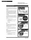
Basic Installation Steps
1. Mount the RSP12(s) on the panel accessory bracket.
2. Wire 24V rectified power from the panel motherboard
to the blue and white power input tabs on the RSP12.
3. Wire red and black connections for each relay from
the panel motherboard to relay outputs on the RSP12.
4. Wire any 2- or 3-wire switch to the individual switch
inputs and/or the Master switch input on the RSP12
(not on the panel motherboard).
5. Select additional control functions.
Installation in an Accessory Cabinet near the LAP
Accessory cabinets with covers include:
RBS1 Accepts one (1) RSP12
RBS2 Accepts two (2) RSP12s
Mount the RSP12 in the accessory cabinet and wire the
same as above.
2.
WIRE
24 VOLT
RECTIFIED
POWER
4. WIRE ANY 2- OR 3-WIRE SWITCHES
1. MOUNT RSP12 IN PANEL
3.
WIRE
RELAYS