


7
GEAppliances.com
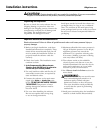
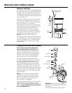
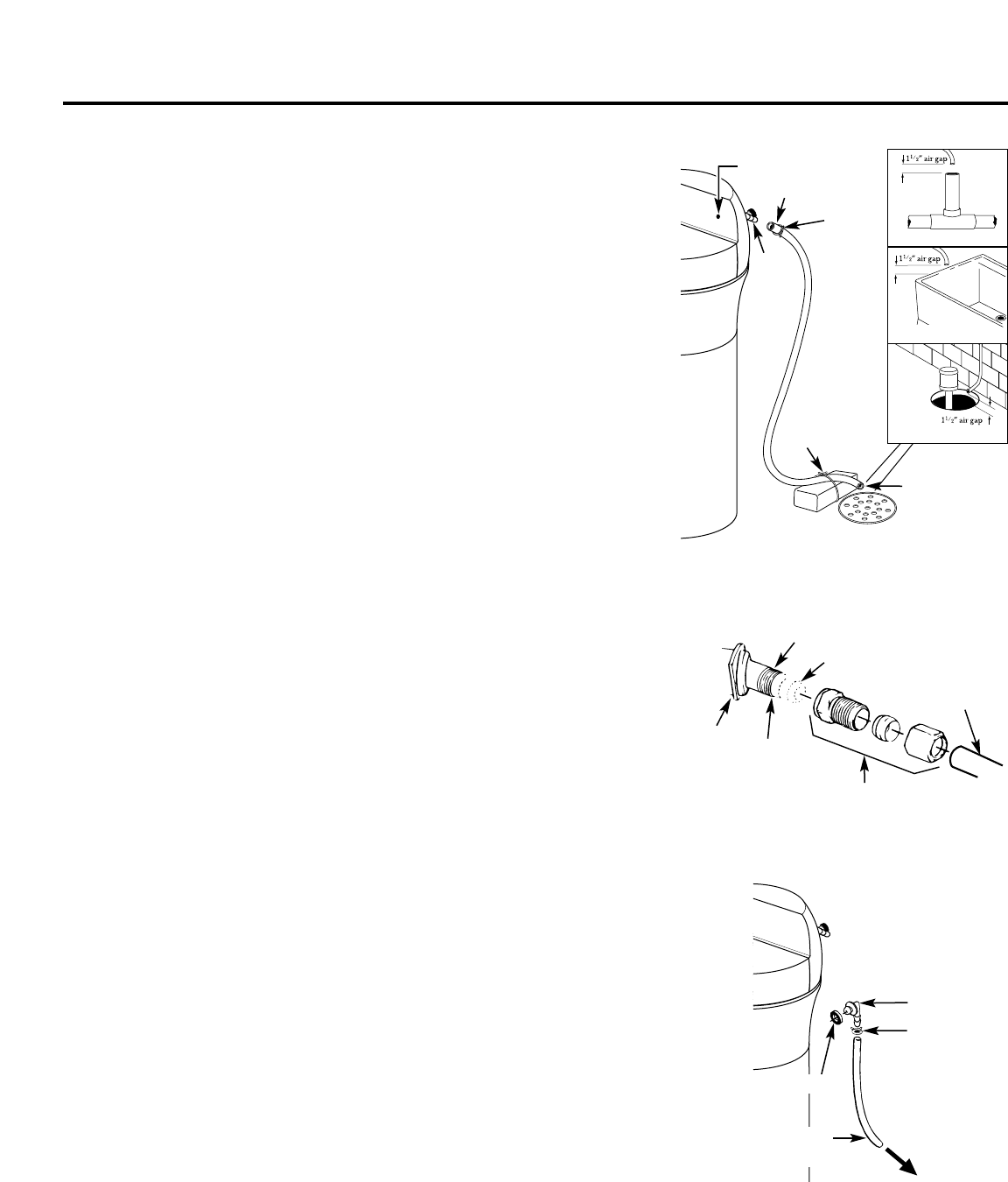
Fig. 4A
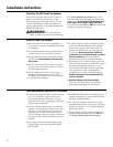
Fig. 5
To sewer drain
Overflow
drain hose
Hose clamp
Grommet
Clip
1/4″ NPT threads
Barbs
1/2″ O.D.
copper tube
(not furnished)
Cut barbs
from drain
fitting
Compression fitting,
1/4″ NPT X 1/2″ O.D. tube
(not furnished)
Do not connect to
valve drain hose.
Hose adapter
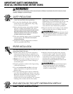
Fig. 4
Drain
fitting
on valve
Valve drain hose
FLOOR DRAIN
Tie or wire
hose in place
1
1
⁄2″ air gap
LAUNDRY TUB
SUMP
Clamp
STANDPIPE
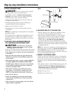
Blue indicator light
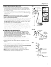
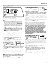
4. CONNECT AND RUN THE VALVE DRAIN HOSE
• Use the provided drain hose (20′ length included) to attach to the
valve drain fitting. To keep water pressure from blowing the hose off,
use a hose clamp to secure in place. Cut the necessary length and use
the remainder in Step 5.
• Locate the other end of the hose at a suitable drain point (floor drain,
sump, laundry tub, etc.) that terminates at the sewer. Check and comply
with local codes.
IMPORTANT: If more drain hose is needed, it should be ordered from
GE Parts at 800.626.2002. The water softener will not work if water
cannot exit this hose during recharge.
• Tie or wire the hose in place at the drain point. High water pressure will
cause it to whip during the back-wash and fast rinse cycles of recharge.
Also provide an air gap of at least 1
1
⁄2″ between the end of the hose and
the drain point. An air gap prevents possible siphoning of sewer water
into the softener, if the sewer should “back-up.”
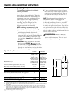
• Elevating the drain hose may cause back pressure that could reduce
the brine draw during recharge. If raising the drain line overhead is
required to get to the drain point, measure the inlet water pressure to
the softener first. For inlet pressures between 20 and 50 psi, do not raise
higher than 8′ above the floor. For inlet pressure above 50 psi, the drain
line may be raised to a maximum height of 14′.
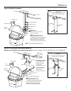
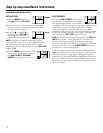
4A. CONNECTING A RIGID VALVE DRAIN TUBE
To adapt a copper drain tube to the softener, use a hacksaw to cut the
barbed end from the drain fitting as shown in Fig. 4A. Rotate the drain
fitting so the cutting blade clears the valve housing to prevent damage to
valve. Buy a compression fitting (1/4″ female pipe thread x 1/2″ O.D. tube)
and needed tubing from your local hardware store.
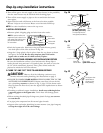
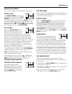
5. INSTALL THE BRINE TANK OVERFLOW FITTINGS AND HOSE
• Insert the rubber grommet into the 3/4″ diameter hole in the brine
tank sidewall as shown in Fig. 5.
• Push the end of the hose adapter elbow into the grommet as shown
in Fig. 5.
• Attach a length of hose (use remaining hose from Step 4) to the hose
adapter elbow. Use a hose clamp to hold it in place.
• Locate the other end of the hose at the drain point. DO NOT ELEVATE
this hose higher than the elbow on the brine tank.
IMPORTANT: DO NOT TEE OVERFLOW HOSE TO VALVE DRAIN HOSE.
NOTE: This drain is for safety only. If the cabinet (brine tank) should
over-fill with water, the excess is carried to the drain.