Customer ServiceTroubleshooting TipsOperating InstructionsSafety Instructions Installation Instructions
11
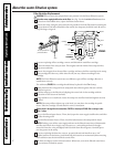
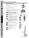
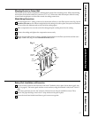
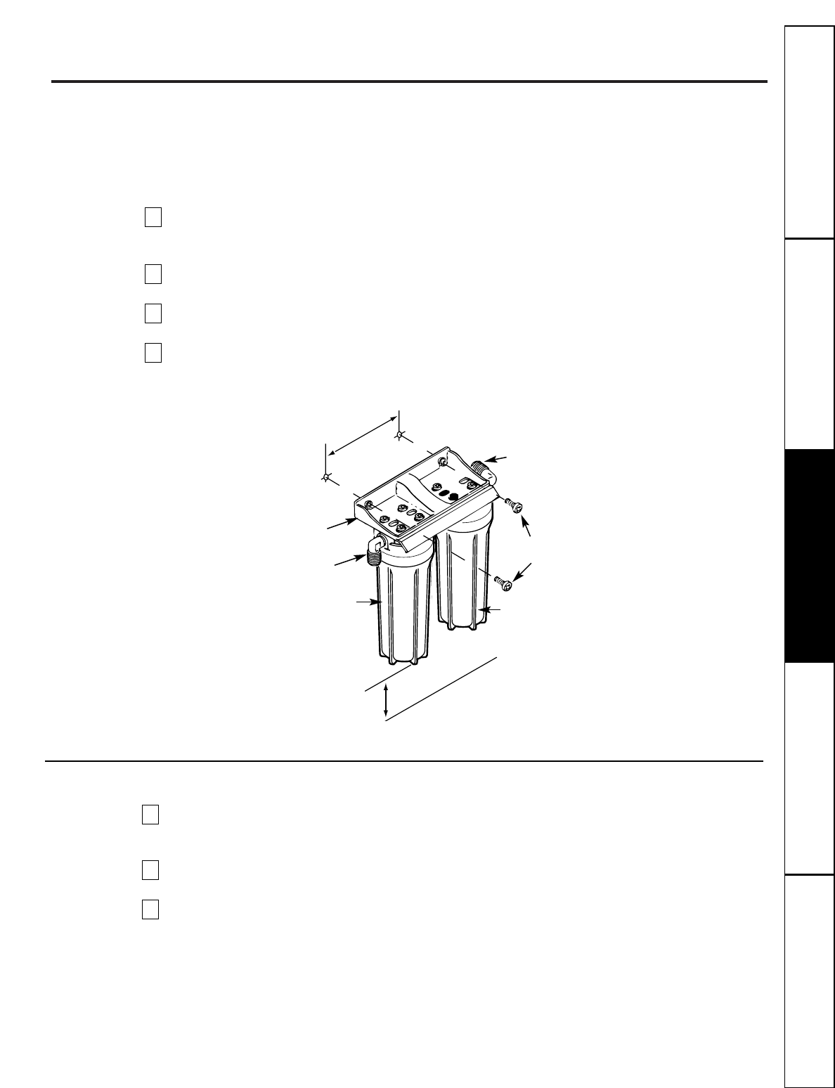
Mounting Bracket to Cabinet Wall
The bracket can be used as a template for marking the location of the mounting screws. When determining
the
location of the bracket make sure you leave 1-1⁄ 2″ to 2″ of free area under the sumps to allow for sump
removal and enough space on either side to make the tubing connections.
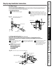
Make Tubing Connections
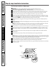
Run the length of 3⁄8″ tubing, connected to the bottom of faucet, to the filter system outlet, Fig.1 in the
Installation Overview
section. Allow enough slack in the tubing to be able to place the system on the floor
in front of the sink. Measure and cut the end of the tubing square.
Slide a compression nut onto the end of the tubing and push a tubing insert into the tubing.
Connect the tubing and tighten the compression nuts securely.
Repeat the preceding steps to connect a length of tubing between the filter system inlet and the water
supply/saddle valve, Fig. 1 in the
Installation Overview
section.
4
3
2
1
Battery Pack Installation and Connection
In a dry location, within reach of the electronic base 3′ leadwire, select a place for the battery pack (see
Fig. 1 on page 8). The battery pack attaches to most surfaces, using the included “sticky-back” Velcro™
strip.
The battery pack uses two size “AA” batteries. Check to be sure they are installed correctly. Then,
remove the paper backing on the Velcro™ strip and secure the pack in place.
Fasten electronic base leadwire and battery pack connector together.
3
2
1
Fig. 4
Filter Ι
Filter ΙΙ
Sump
Mounting
screws
Tubing
connector
Tubing
connector
Mounting
bracket
Sump
7-9⁄16″
1-1⁄2″ to 2″


