1057308A • February 2007
Copyright © 2007, GE Security Inc.
SmartCom Room Station
Installation Instructions
Introduction
This is the GE SmartCom Room Station Installation Instructions
for model CC-SCRS01. This document describes how to mount
and wire the room station.
SmartCom provides a modular, expandable system for the distri-
bution of music and intercom functions throughout the home.
The SmartCom room station (Figure 1) provides a single, conve-
nient graphical LCD keypad to control the SmartCom audio and
intercom systems.
Figure 1. SmartCom room station
Prewire requirements
Prewired and preinstalled CAT5 cable and low-voltage double-
gang deep box or mud ring.
Note: You may need a second cable if the homeowner wants to
upgrade the keypad to the GE SmartCom touch-screen
model in the future.
Required equipment
You will need the following equipment to install the room
station:
• EZ RJ45 ratchet-style crimper
• Phillips screwdriver
Installation
Terminate the CAT5 cables used to connect the room station with
an RJ45 plug using the TIA 568A residential standard configura-
tion. Proper installation of the CAT5e plug is critical to maintain
5e rating of the cable (see Cable preparation on page 1).
Mounting the room station
To mount the room station, do the following:
1. Press the tab on the bottom of the base and lift the face plate
off the base.
2. Mount the back plate to a double-gang, low-energy box
using the mounting screws provided. Do not overtighten the
screws.
3. Connect the cable as appropriate (see Wiring).
4. Line up the top of the face plate with the top of the base and
press the tab on the base while you fit the face plate to the
base. Release the tab to secure the face plate to the base.
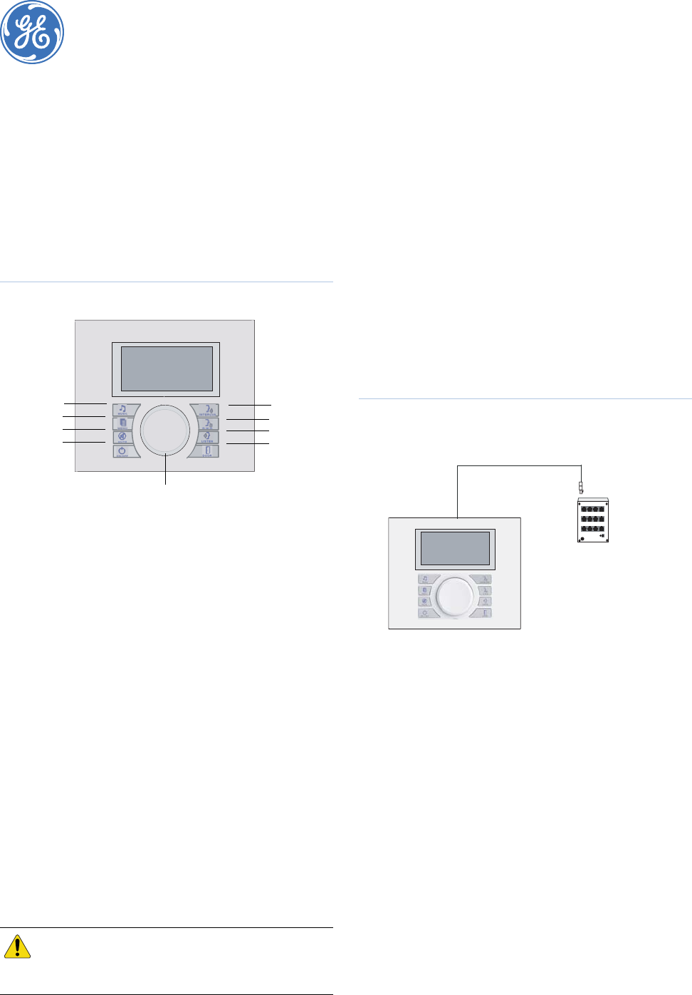
Wiring
You can use up to 200 ft. (61 m) of cable between the room
station and the SmartCom intercom hub.
To connect the room station to the intercom hub, do the
following:
1. Run cable from the room station to the inputs on the front of
the intercom hub.
2. Label both ends of the wire with the room station number.
3. Plug one end of the cable into the back of the room station
and the other end into any room station jack on the front of
the intercom hub (Figure 2).
Refer to your intercom hub documentation for more details.
Figure 2. Room station wiring diagram
Cable preparation
To add an RJ45 connector to the cable, do the following:
1. Use a CAT5e stripper to score the outer jacket about 2 in.
(51 mm) from the end of the cable.
Note: Do not cut the cable with the stripper.
2. Use your fingers to bend the outer jacket back and forth
until the jacket breaks off.
3. Cut the spline so that it does not protrude from the outer
jacket. Be careful not to nick the wires.
4. Untwist the wires and flatten them until all kinks are
removed.
5. Slide 0.25 in. (6 mm) of the outer jacket over the spline.
6. Trim the wires to 1.5 in. (38 mm) from the outer jacket.
7. Arrange the wires in the correct color code sequence
according to the T568A pin out configuration.
8. Slide the wires into the RJ45 plug, keeping them in the
correct color sequence. The tips of the wires will protrude
from the end of the connector.
9. Continue sliding the wires all the way into the plug until
about 0.25 in. (6 mm) of the outer jacket is inside the plug.
The cable should stop sliding in when the spline touches the
connector.
10. Crimp the connector using the EZ RJ45 ratchet-style
crimper. The crimper will crimp then cut the wires. Use
your fingers to finish breaking off the wires.
CAUTION: You must use the flathead screws
provided or damage to the room station
will occur.
. . . . .
. . . .
. . . . .
. . . .
. . . . .
. . . .
. . . . .
. . . .
. . . . .
. . . .
. . . . .
. . . .
. . . . .
. . . .
. . . . .
. . . .
. . . . .
. . . .
. . . . .
. . . .
. . . . .
. . . .
. . . . .
. . . .
. . . . .
. . . .
. . . .
. . . .
. . . .
. . . .
. . . .
. . . .
. . . .
. . . .
. . . .
. . . .
. . . .
. . . .
. . . .
. . . .
. . . .
. . . .
. . . .
. . . .
. . . .
. . . .
. . . .
. . . .
. . . .
. . . .
. . . .
. . . .
CD PLAYER
Return to system alarm
OOOOO All Doors
ON
Selection knob
Intercom
controls
Intercom
DND
Listen/Mon
Door
Music
controls
Music
Menu
Music mute
On/off
. . . . .
. . . .
. . . . .
. . . .
. . . . .
. . . .
. . . . .
. . . .
. . . . .
. . . .
. . . . .
. . . .
. . . . .
. . . .
. . . . .
. . . .
. . . . .
. . . .
. . . . .
. . . .
. . . . .
. . . .
. . . . .
. . . .
. . . . .
. . . .
. . . . .
. . . .
. . . . .
. . . .
. . . . .
. . . .
. . . . .
. . . .
. . . . .
. . . .
. . . . .
. . . .
. . . . .
. . . .
. . . . .
. . . .
. . . . .
. . . .
. . . . .
. . . .
. . . . .
. . . .
. . . . .
. . . .
. . . . .
. . . .
CD PLAYER
Return to system alarm
OOOOO All Doors
ON
CAT5 or CAT5e
Room stations
1 to 8
Intercom
hub


