


WARNING: The pressure
rating of the relief valve
must not exceed 150 PSI,
the maximum working
pressure of the water
heater as marked on
the rating plate.
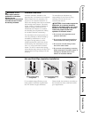
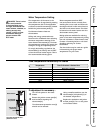
A new combination temperature and pressure relief valve, complying with the Standard for Relief Valves
and Automatic Gas Shut-Off Devices for Hot Water Supply Systems, ANSI Z21.22, is supplied and must
remain installed in the opening provided and marked for the purpose on the water heater. No valve of any
type should be installed between the relief valve and the tank. Local codes shall govern the installation of
relief valves.
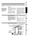
Relief Valve
The Btuh rating of the relief valve must
not be less than the input rating of the
water heater as indicated on the rating
label located on the front of the heater
(1 watt=3.412 Btuh).
Connect the outlet of the relief valve
to a suitable open drain so that the
discharge water cannot contact live
electrical parts or persons and to
eliminate potential water damage.
Piping used should be of a type approved
for hot water distribution. The discharge
line must be no smaller than the outlet
of the valve and must pitch downward
from the valve to allow complete
drainage (by gravity) of the relief valve
and discharge line. The end of the
discharge line should not be threaded or
concealed and should be protected from
freezing. No valve of any type, restriction
or reducer coupling should be installed in
the discharge line.
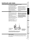
To Fill the Water Heater
WARNING: The tank must be full of
water before heater is turned on. The
water heater warranty does not cover
damage or failure resulting from
operation with an empty or partially
empty tank. (Refer to the Certificate of
Limited Warranty for complete terms
and conditions.)
Make certain the drain valve is completely
closed.
Open the shut-off valve in the cold water
supply line.
Open each hot water faucet slowly to
allow the air to vent from the water
heater and piping.
A steady flow of water from the hot water
faucet(s) indicates a full water heater.
Safety Instructions Installation Instructions Operating Instructions Care and Cleaning Troubleshooting Tips Customer Service
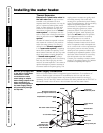
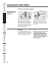
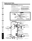
Typical Top Connect Installation
HOT
C
O
L
D
E
L
I
E
F
A
L
V
E
Anode
To electrical
distribution panel
Temperature & pressure relief
valve
Electrical junction box
(use only copper conductors)
Relief valve
discharge line.
Directed to under
side of home.
Union
Hot water outlet to fixtures
Heat trap
6″ Min.
Heat trap
6″ Min.
Jacket access
panel
Union
Jacket access
panel
Shut-off valve
To cold water
supply
Auxiliary
catch pan
Drain valve
7