


16
Installation Instructions
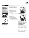
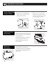
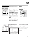
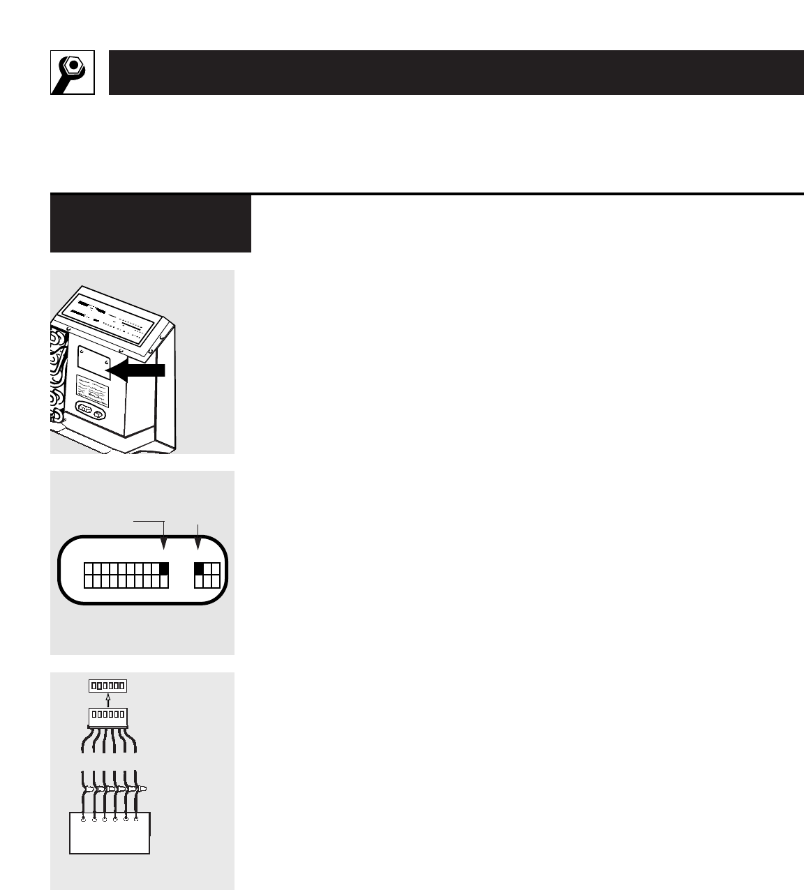
The Zoneline can be controlled
by using the controls on the unit
or by a wall thermostat.
Detailed wiring instructions are
packed with the low-voltage con-
nectors in the recessed connection
space on the Zoneline chassis.
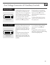
To switch to a wall thermostat,
move switch 10 to the
ON
(up)
position (see illustration B at left).
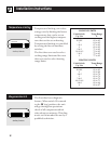
Connect the unit to a 6-wire Class 2
Remote Thermostat (GE Model
RAK147 or equivalent), as shown
in illustration C at left.
For some applications, it may be
desirable to operate on low fan
speed. Moving the auxiliary switch
11 to the
ON
(up) position will pro-
vide low fan speed in both heating
and cooling modes.
No external voltage may be applied
to the unit through the Remote
Thermostat terminals.
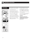
IMPORTANT:
After the wire connections are
completed, replace the metal cover
to prevent damage to the unit or
personal injury.
Remote Control/
Wall Thermostat
10 11
ON
OFF
ON
OFF
RED
GRY
BLK
YEL
WHT
BLU
+24V
FAN MOT.
SOL. COIL
COMP.
HEATER
GND
1
Class 2
Remote
Thermostat
Low fan speed
with Class 2
Remote
Thermostat
Auxiliary Controls
Class 2 Thermostat
RAK147
or equivalent
R C T’Stat terminalsG B Y W
Wire nut
6 PCS
6P Plug
Insert
B
C
A
Metal
cover
over
recessed
connection
space