2
Brine Valve PN 3020511
Brine Well Installation
1. The brine well should be vertically installed in the
regenerant tank.
2. All connections should be manually tightened to
ensure a solid connection. DO NOT over tighten plastic
parts with a wrench, or you might damage plastic
components.
3. Set the postion of the brine valve float. The float
should be positioned 0.8" - 2" (20 - 50 mm) above the
brine surface level or as required for application.
CAUTION: DO NOT use petroleum based lubricants such as
vaseline, oils, or hydrocarbon based lubricants. Use only
100% silicone lubricant.
Operation
The brine valve will work with the control valve to
automatically control the water level in the brine tank.
Another unique feature of the brine valve is the ability to
adjust the top support. The top bracket can be moved up
or down by loosening the lock nut. Hand tighten the
locknut.
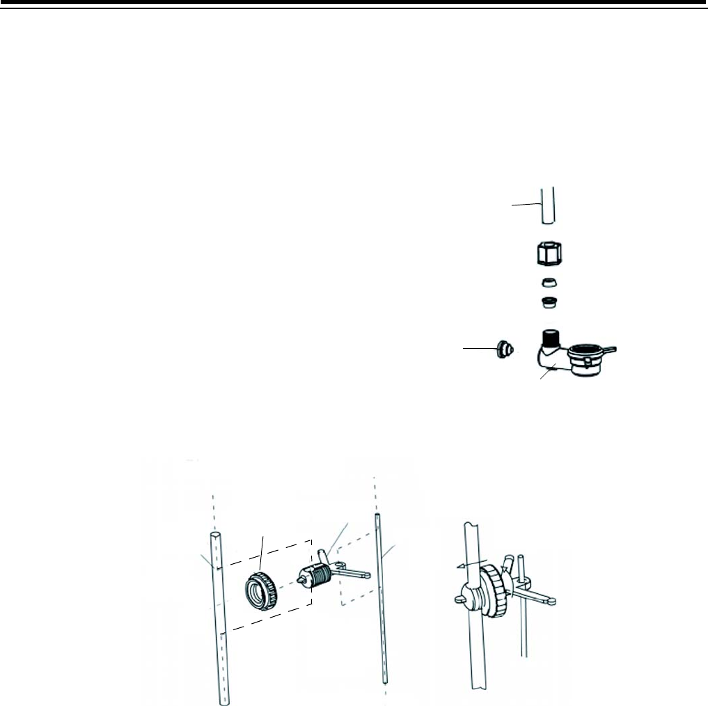
Figure 2
Figure 3
Regenerant Tube
Base Plug
Valve Base
Disassembly
Assembly
Regenerant Tube - 3/8"
1/2” Lock Nut
Adjust Bracket
Plastic Tube
Arrow Direction to Tighten


