


7
3
4
"
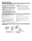
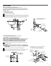
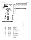
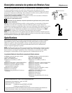
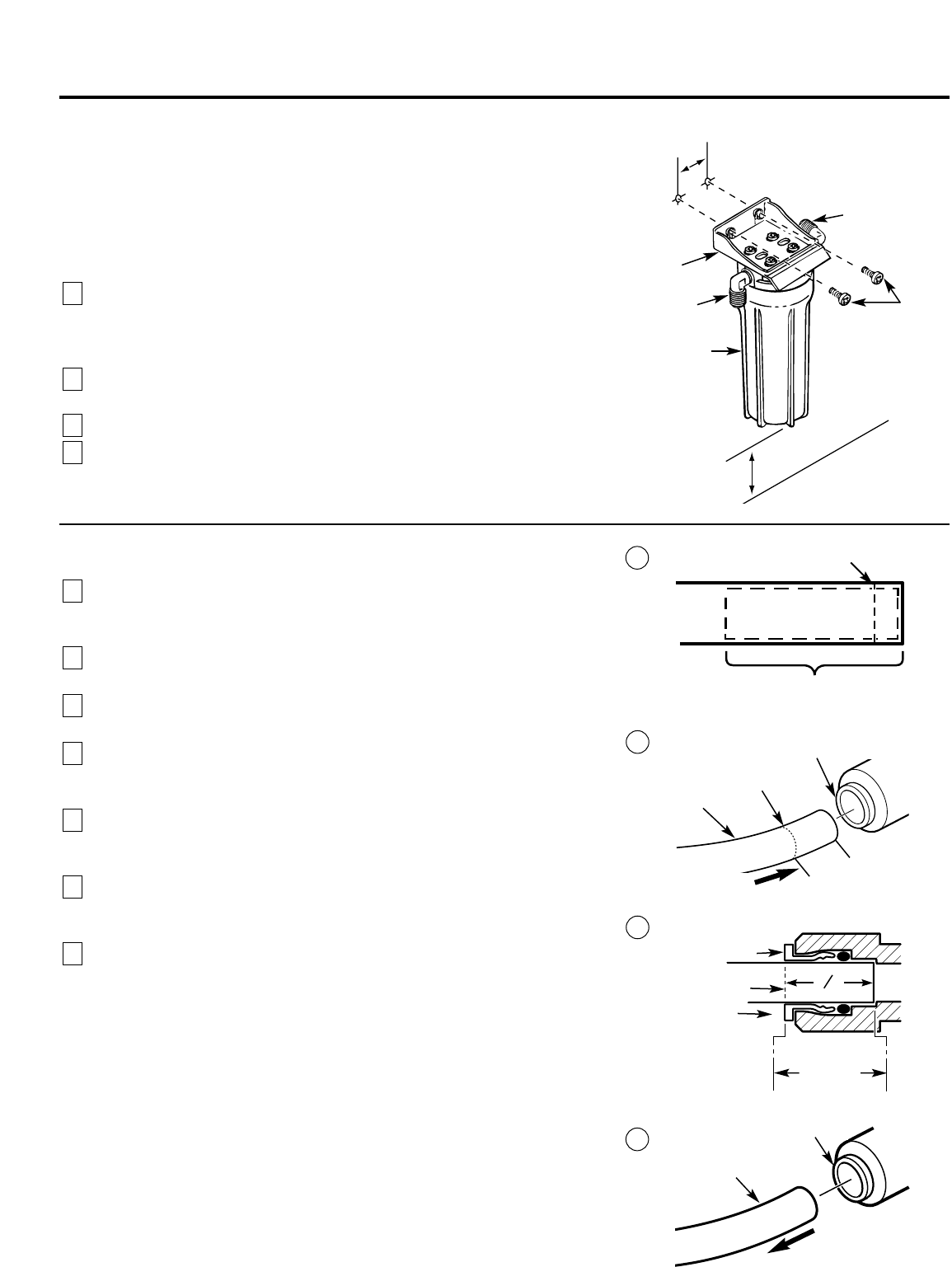
Mounting Bracket to Cabinet Wall
The bracket can be used as a template for marking the location of the
mounting screws. When determining the
location of the bracket make sure
you leave 1-1⁄2
″
to 2
″
of free area under the sumps to allow for sump removal
and enough space on either side to make the tubing connections.
Tubing Connections—Compression Style
(Models GX1S04C and GN1S04C)
Run the length of 3⁄8″ tubing, connected to the bottom of faucet,
to the filter system outlet. Allow enough slack in the tubing so the unit
can be easily removed for filter changes. Measure and cut the end of
the tubing square.
Slide a compression nut onto the end of the tubing and push a tubing
insert into the tubing.
Connect the tubing and tighten the compression nuts securely.
Repeat the preceding steps to connect a length of tubing between
the filter system inlet and the water supply/saddle valve (illustration in
the Installation Overview section).
4
3
2
1
Mounting
screws
Tubing connector
(outlet)
Tubing connector
(inlet)
Mounting
bracket
Sump
2-3⁄4″
1-1⁄2″to 2″
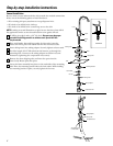
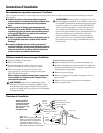
Tubing Connections—Push-In Style (Model GX1S15C [rev. 2])
Run the length of the 3⁄8″ tubing, connected to the bottom of the faucet,
to the filter system outlet (illustration above). Allow enough slack in the
tubing so that the unit can be easily removed.
Measure and cut the end of the tubing square using a sharp cutter or
knife. Remove any burrs (illustration A).
Inspect the end of the tubing, about 1 inch, to be sure there are no
imperfections. It may be necessary to cut the tubing again.
Mark the tubing for length of insertion. For 3/8″ OD tubing the insertion
length should be approximately 3/4 of an inch. Tubing must be fully
inserted to avoid leaks.
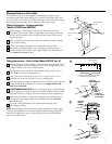
DO NOT REMOVE GRAY COLLET. Push the tubing all the way into the fitting
until it bottoms out. The insertion line should be hidden or barely visible
(illustration B and C). Slightly pull on the tubing to verify engagement.
Repeat the procedure to connect the tubing between the filter system
inlet and the water supply/saddle valve (illustration in the Installation
Overview section).
To remove tubing (illustration D), depress and hold gray collet.
Pull tubing to remove.
NOTE: Avoid installing the unit where the tubing is pulled at a sharp angle.
This type of installation may cause the fittings to leak. If using tubing other
than what is supplied, be sure it is high quality, exact size and roundness,
and has a smooth surface.
7
6
5
4
3
2
1
Engagement
3/4″(3/8″ tubing)
Gray Collet
(DO NOT
REMOVE)
Gray Collet
Tubing
Cut tubing square
End of tubing round and smooth, with no cuts,
nicks or flat spots (approximately 1″)
Insertion line
A
C
D
Depress gray collet
and pull tubing
to remove
Insert tubing
B
Insert
Gray Collet
(DO NOT REMOVE)
Insertion line
Tubing
Tubing must
be fully inserted
to avoid leaks.
3⁄4″