


21
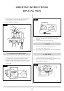
If the stove has been installed in a restrictive location, it
may be necessary to remove the stove from its location.
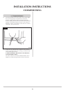
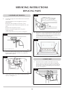
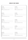
9.1 Locate the sensor in the draught diverter opening, and
gently pull the two wires off the terminals. Undo the two
taptite screws and remove the sensor and the two plastic
spacers. See diagram 14.
9.2 Refit a new sensor ensuring the spacers are located between
the sensor and the bracket. Replace the two leads.
9.3 If it has been necessary to remove the stove, ensure that all
disturbed gas joints are checked for gas soundness when
reinstalled, and repeat the flue clearance test as detailed in
the Commissioning Section.
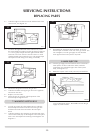
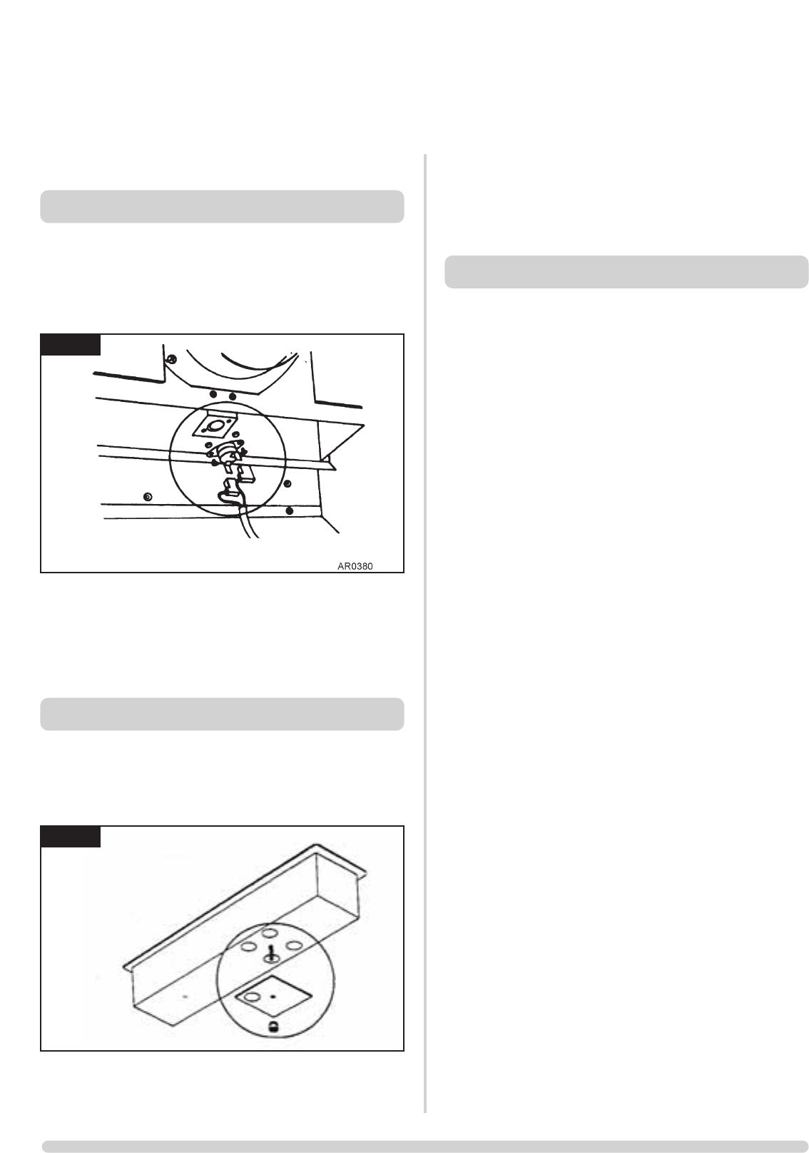
10.1 Turn the gas supply off at the isolation device.
10.2 Locate the aeration plate on the underside of the airbox
and remove the Nyloc nut, see diagram 15.
10.3 Remove the plate and replace with the correct size, ensure
that the hole(s) in the plate align correctly with the holes in
the underside of the airbox and replace the Nyloc nut.
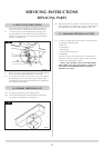
11.1 In order to change between gas types, it will be necessary
to change the following items.
• Pilot Unit
• Control Valve
• Main Injector
• Aeration Plate (if required)
• Databadge
The relevant parts can be ordered as a conventional kit
from Gazco. Always quote the appliance type and serial
number when ordering spare parts.
** NOTE: THE CONTROL VALVE IS FACTORY PRESET
FOR CORRECT GAS TYPE AND MODEL. A NEW UNIT
WILL NEED TO BE ORDERED WHEN CHANGING
BETWEEN GAS TYPES.
SERVICING INSTRUCTIONS
REPLACING PARTS
14
15
9. GAZCO FLUE SURE SYSTEM
10. PRIMARY AERATION PLATE
11. CHANGING BETWEEN GAS TYPES
AR0381