


En-2
°F
NON STOP
AMPM CLOCK
AMPM
TIMER
NEXT DAY
DAY
OFFON
TIMER
WEEKLY
AUTO
OFF
ON
OFF
ON
DAY OFF
DEFROST
TEST
21
AUTO
HEAT
FAN
COOL
TIMER
MODE
SET
ZONE
START/STOP
CLOCK ADJUST
SET TIME TEMP./DAY FAN
CONTROL
MASTER
CONTROL
DAY OFF
ENERGY SAVE
°F
NON STOP
AM CLOCK
AUTO
F
E
D
C
0
A 79
B 8 6
I
H
L
G
J K
M
NO PQR
S
T
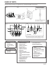
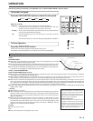
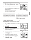
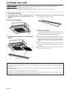
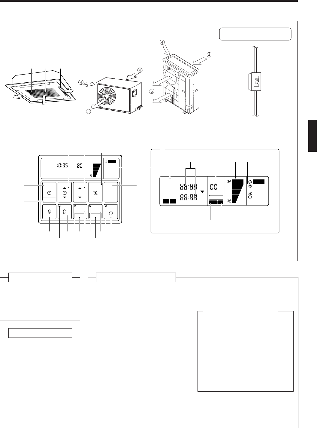
NAME OF PARTS
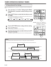
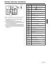
Fig. 1
Fig. 2
This breaker is installed during
the electrical installation.
Electrical Breaker
Fig. 3
Fig. 4
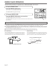
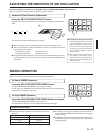
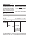
● For explanatory purposes, the figure showing the remote
controller display shows all possible displays. The actual
display shows only that area that is being adjusted or used.
Fig. 5 Display
Fig. 1 Indoor Unit
1 Air Filter
2 Air Intake Grille
3 Air Flow Direction
Flaps
Fig. 2 Outdoor Unit
4 Air intake
5 Air outlet
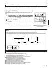
Fig. 4 Remote Controller
6 START/STOP Button
7 Operation Lamp
8 ENERGY SAVE Button
9 DAY OFF Button
0 ENERGY SAVE Lamp
A ZONE Control Button
B SET Button
C ZONE Control Lamp
D AIR FLOW DIRECTION SWING
Button
E AIR FLOW DIRECTION SWING
Lamp
F AIR FLOW DIRECTION SET Button
G CLOCK ADJUST Button
H TIMER MODE Button
I SET TIME Button
J TEMP./DAY Button
M Remote Controller Display
(Fig. 5)
N Timer Mode Display
O Clock Display (CLOCK/TIMER)
P Set Temperature Display
(TEMP.)
Q Fan Speed Display
R Operation Mode Display
S DEFROST Display
T TEST Display
Instructions relating to heating (*) are applicable only to “HEAT & COOL MODEL” (Reverse Cycle).
K FAN CONTROL Button
L MASTER CONTROL Button
13
2