


4
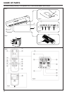
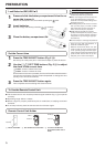
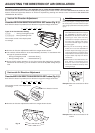
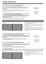
Fig. 1 Indoor Unit
1 Operating Control Panel (Fig. 2)
2 MANUAL AUTO button
3 Remote Control Signal Receiver
4 Indicator Lamps (Fig. 3)
5 OPERATION Indicator Lamp
(green ...... COOL, DRY, FAN)
(red .......... *HEAT)
6 TIMER Indicator Lamp (yellow)
7 SWING Indicator Lamp (orange)
(VERTICAL/HORIZONTAL SWING)
8 AIR CLEAN Indicator Lamp (green)
●
If the TIMER indicator lamp flashes when
the timer is operating, it indicates that a
fault has occurred with the timer setting
(See page 19 Auto Restart).
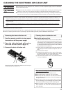
9 Intake Filter (Fig. 4)
; UP/DOWN Air Direction Flaps
A RIGHT/LEFT Air Direction Louvers
(behind UP/DOWN Air Direction Flaps)
B Drain Hose
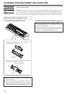
C Electronic Air Clean Unit (Fig. 4)
Fig. 5 Outdoor Unit
D Intake Port
E Outlet Port
F Pipe Unit
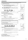
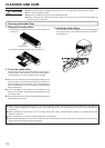
Fig. 6 Remote Control Unit
G AIR CLEAN button
H MASTER CONTROL button
I SET TEMP./SET TIME buttons (
)
J Signal Transmitter
K TIMER button
L FAN CONTROL button
M START/STOP button
N AIR FLOW DIRECTION
VERTICAL SET button
O AIR FLOW DIRECTION
VERTICAL SWING button
P AIR FLOW DIRECTION
HORIZONTAL SET button
Q AIR FLOW DIRECTION
HORIZONTAL SWING button
R TIME ADJUST button
S ACL button
Rear side (Fig. 7)
T TEST RUN
● Touch the two metal contacts with a me-
tallic object to send the signal to perform
a test run.
● Perform a test run only when installing the
air conditioner. If the signal to perform a
test run is received during normal opera-
tion, the air conditioner’s thermostat will
malfunction.
● If the signal to perform a test run is re-
ceived during normal operation, the unit
will switch to the test operation mode and
the indoor unit’s OPERATION and TIMER
indicator lamps will flash simultaneously.
● To stop the test operation mode, press the
START/STOP button to stop the air condi-
tioner.
U Remote Control Unit Display (Fig. 8)
V Transmit Indicator
W Clock Display
X Operating Mode Display
Y Timer Mode Display
Z Fan Speed Display
[ Temperature Set Display
\ Timer Set Indicator
] Temperature Set Indicator