WARNING
(1) Remove the cord clamp.
(2) Process the end of the connection cords
to the dimensions shown in Fig.19.
(3) Connect the end of the connection cord
fully into theterminal block.
(4) Fasten the connection cord with a cord clamp.
(5) Fasten the end of the connection cord with the screw.
(6) The power cable and connecting cable are self-provided.
(1) Always use a special branch circuit and install a special receptacle to supply power to the room air
conditioner.
(2) Use a circuit breaker and receptacle matched to the capacity of the room air conditioner.
(3) The circuit breaker is installed in the permanent wiring. Always use a circuit that can trip all the
poles of the wiring and has an isolation distance of at least 3mm between the contacts of each pole.
(4) Perform wiring work in accordance with standards so that the room air conditioner can be
operated safely and positively.
(5) Install a leakage circuit breaker in accordance with the related laws and regulations and electric
company standards.
23
Installation of Indoor Unit
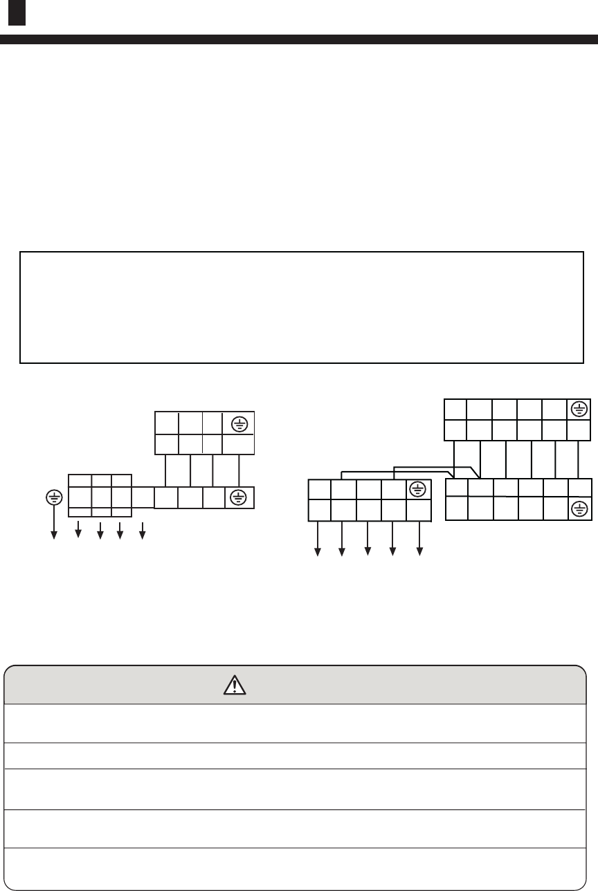
OUTDOOR UNIT
TERMINIAL BLOCK
INDOOR UNIT
TERMINIAL BLOCK
POWER SUPPLY:
3N~,380-400V,50Hz
R S T
N 1 2 3
1 2 3
W B R Y/G
Y/G
Fig. 19
Wiring Connection:
HCFU-42CF03
Note:Connect the black terminal of indoor unit with the black terminal of outdoor unit pro-
perly using the connecting wire which has both white terminals in the accesory bag,
and connect the blue terminal of indoor unit with the white terminal of out terminal as
the same(For heat pump model).For cooling only unit,just connect the black terminal
of indoor unit with the black terminal of outdoor unit properly.
L
N
345
L
N
34 5
R
S
TN
INDOOR UNIT
TERMINIAL BLOCK
OUTDOOR UNIT
TERMINIAL BLOCK
HCFU-42HF03
(7) L,N and 1,2 are equal on the terminal block.
3N~,380-400V,50Hz


