


7
920-197-00
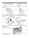
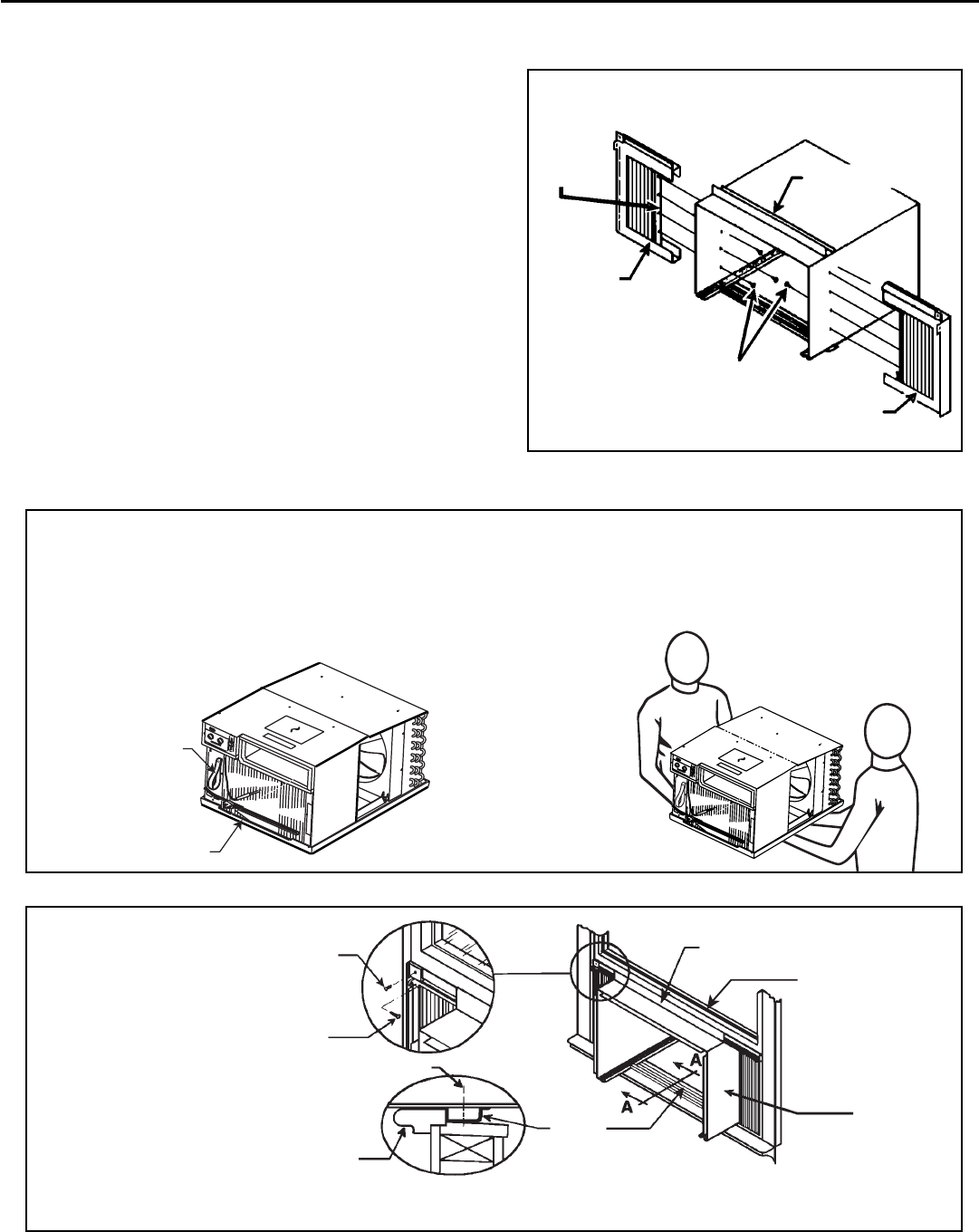
Sash window installations
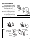
STEP 1 After removing the unit from shipping carton, remove tape holding
decorative front in place. Lay front in a safe out-of-the-way place, then
slide chassis out of cabinet (see Figure A).
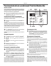
STEP 2 Attach curtain assemblies to cabinet as shown in Figure B. Use eight
(8) No. 8 x ⅜" slotted hex head screws (item #1, page 6).
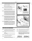
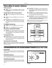
STEP 3 Center cabinet in window with sill channel positioned against
window stool as shown in Figure C, Section A-A.
STEP 4 Pull window sash down behind Shell Support Channel on top of
cabinet; this helps hold cabinet in place. Install No. 8 x ⅞" hex
head screw (item #3, page 6) in sill channel at bottom of window
opening as shown in Figure C.
STEP 5 Extend the sliding curtains on each side so the frames fi t into
the window channels. While holding the curtain frames in place,
mark four (4) hole locations (hole locations are in the upper
corners on left and right curtain assembly), two (2) in the
window jamb and two (2) in the window sash. Slip the curtains
back from marked locations and drill four (4)
7
/
64
" diameter pilot
holes. Again, extend the sliding curtains on each side and then
install two (2) no. 8 x ½" Phillips head screws (item #2, page 6)
and two (2) No. 8 x 1 ¼" Phillips head screws (item #4) through
the curtain frames as shown in Figure C.
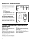
Figure A
BASEPAN HANDLE
PULL STRAP
TO PULL UNIT FROM SLEEVE, USE PULL STRAP AND BASEPAN
HANDLE LOCATED ON FRONT. OBTAIN ASSISTANCE OR HELP
AS NECESSARY TO HOLD SLEEVE WHILE PULLING UNIT FROM
SLEEVE. MAKE SURE AIR CONDITIONER IS ON FIRM SUPPORT
BEFORE REMOVING UNIT FROM SLEEVE.
WHEN CARRYING OR HANDLING UNIT, OBTAIN ASSISTANCE OR
HELP AS NECESSARY TO SUPPORT UNIT FROM BOTTOM (BASE
PAN), MAINTAINING CLEARANCE FROM ALL OBSTACLES.
CURTAIN
ASSEMBLY
RETAINING
BRACKET
CURTAIN
ASSEMBLY
(LEFT)
SHELL SUPPORT
CHANNEL
Figure B
SCREW #8 x ⅜" SLOTTED HEX HEAD
(ILLUSTRATION ON PAGE 6, ITEM #1)
8 REQUIRED (4 EACH SIDE). INSTALL
FROM INSIDE SLEEVE TO CURTAIN
ASSEMBLY RETAINING BRACKET
CURTAIN
ASSEMBLY
(RIGHT)
Figure C
SECTION A-A
SCREW, 1/2” PHILLIPS HEAD
(See illustration, item #2, page 6)
SCREW, 1 1/4” PHILLIPS HEAD
(See illustration, item #4, page 6)
SCREW, #8 x 7/8” HEX HEAD
(See illustration, item #3,
page 6)
WINDOW STOOL
SILL
CHANNEL
SHELL SUPPORT CHANNEL
WINDOW SASH
CABINET