


TEST:
1. Remove leads from thermostat.
2. Turn thermostat knob clockwise to its coldest
position.
3. Test for continuity between the two terminals. Contacts
should be closed.
4. Turn thermostat knob counterclockwise to its warmest
position.
5. Test for continuity - contacts should be open.
NOTE: The thermostat must be within the temperature
range listed to open and close.
To maintain the comfort level desired, a cross ambient type
thermostat is used. The thermostat has a range from 60°
±2°F to 92° ±3°F. The thermos
tat bulb is positioned in front
of the evaporator coil to sense the return air temperature.
Thermostat malfunction or erratic operation is covered in
the troubleshooting section of this manual.
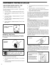
THERMOSTAT (“EQ08” Models)
(See Figure 17)
This thermostat is single pole-double throw, cross ambient
with a range of 60° to 92°F and a differential of ±2°F. Terminal
“2” is common.
Figure 17
Thermostat
(EQ Model)
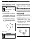
Figure 18
Thermostat
TEST:
Cooling/Heating Models: Remove wires from thermostat
and check continuity between terminal “2” (common) and
“3” for cooling. Check between terminals “2” (common)
and “1” for heating. Also check that contacts in thermostat
open after placing in either position. NOTE: Temperature
must be within range listed to check thermostat. Refer to
the troubleshooting section in this manual for additional
information on thermostat testing.
THERMOSTAT ADJUSTMENT
No attempt should be made to adjust thermostat. Due
to the sensitivity of the internal mechanism and the
sophisticated equipment required to check the calibration,
it is suggested that the thermostat be replaced rather than
calibrated. Thermostat bulb must be straight to insure
proper performance.
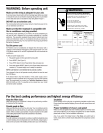
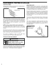
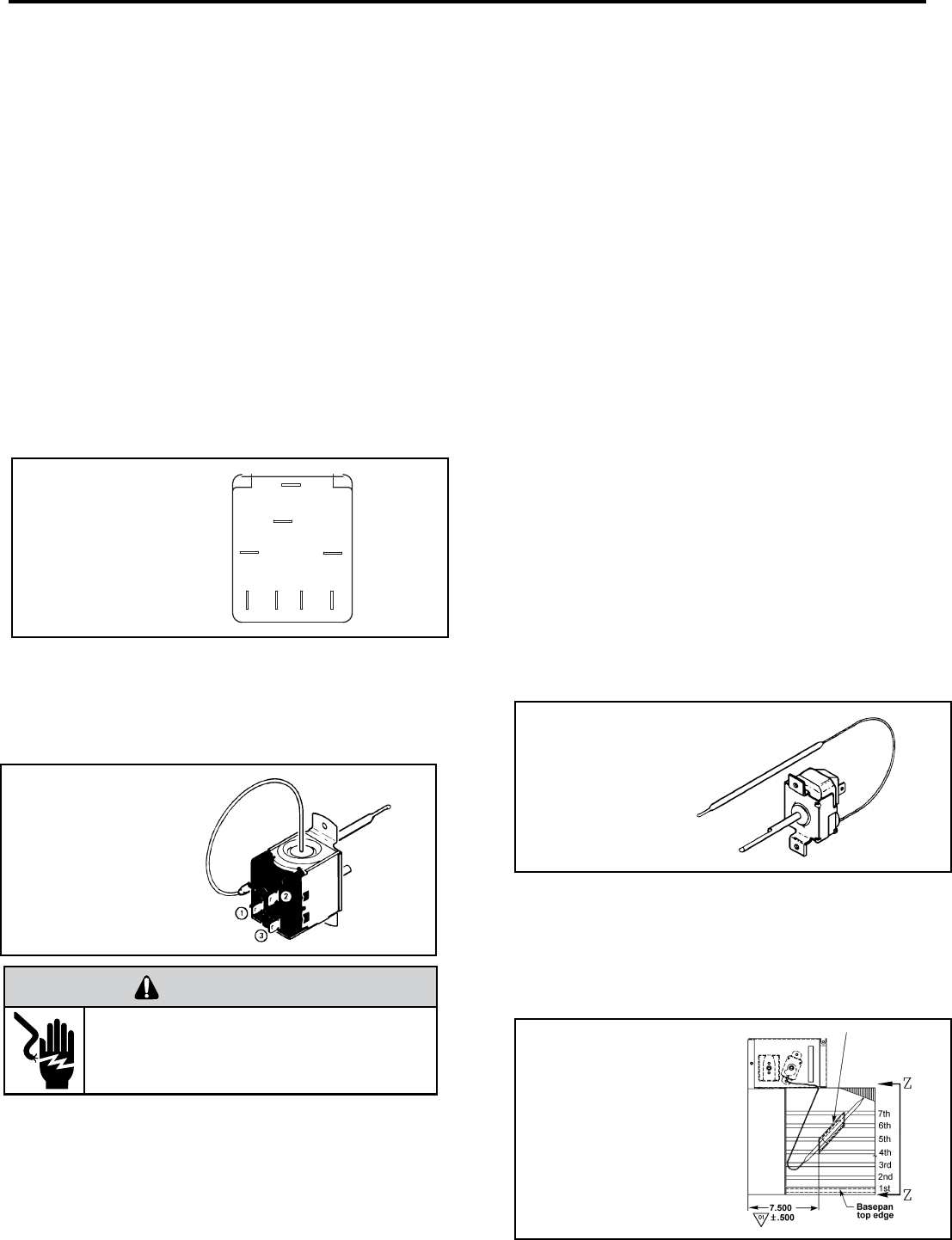
THERMOSTAT BULB LOCATION
The position of the bulb is important in order for the
thermostat to function properly. The bulb of the thermostat
should be located approximately 45° to a maximum of 60°
from horizontal. Also, do not allow the thermostat bulb to
touch the evaporator coil. (See Figures 17 and 18)
Thermostat sensor holder 020
to be positioned between the
4th and 5th and 6th and 7th
rows of tubes from the bottom
of the coil at dimension shown
Figure 19
Thermostat Bulb Location
(EQ Model)
COMPONENTS TESTING (Continued)
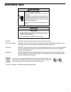
ELECTRIC SHOCK HAZARD
WARNING
Disconnect power to the unit before
servicing. Failure to follow this warning
could result in serious injury or death.
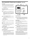
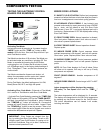
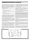
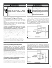
EQ08 SYSTEM CONTROL SWITCH - TEST
“EQ08” SYSTEM CONTROL SWITCH – TEST
Turn knob to phase of switch to be tested. There must be
continuity as follows:
1. “Fan Only” Position – between terminals “MS” and “H”
2. “Hi Cool” Position – between terminals “L1” and “C” and
“MS” and “H”
3. “Low Cool” Position – between terminals “L1” and “C”
and “MS” and “LO”
4. “Low Heat” Position – between terminals “L2” and “2”
and “MS” and “LO”
5. “Hi Heat” Position – between terminals “L2” and “2” and
“MS” and “H”
L1
MS
2
H
LO
C
L2
B1
System Control Switch
(EQ Models)
14