


10
Installation requirements
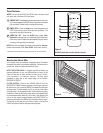
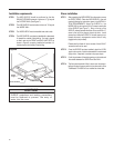
STEP 1 The WSD SLEEVE should be positioned so that the
DRAIN EXTENSION extends a minimum of
9
16
" beyond
the OUTSIDE WALL (See Figure 7).
STEP 2 The WSD SLEEVE must extend a minimum of ⅞" beyond
the INSIDE WALL.
STEP 3 The WSD SLEEVE must be installed level side to side.
Sleeve installation
STEP 1
Please note that there will be an excess of two #12Ax2"
screws that will not be used.
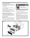
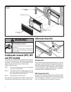
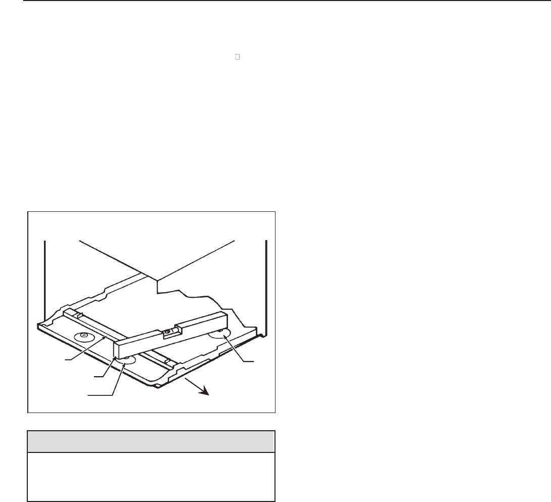
Figure 8
Back Unit Rest
Slope
Front Unit Rest
Level
Raised
Ledge
STEP 4 The WSDSLEEVE must also be installed with a downward
tilt toward the outside of the building. If a level is placed
so that it rests on the FRONT and BACK UNIT REST as
shown in Figure 8, a properly installed unit provides a ½
bubble slope to the outside of the building.
STEP 2 Once the SLEEVE has been installed, check the LEVEL
.deniatniam si tlit drawnwod elbbub ½ eht erus eb ot niaga
Apply shims, if required, to maintain the proper slope.
STEP 3 Caulk the perimeter of the entire opening on the inside and
the outside between the SLEEVE and the WALL.
STEP 4
NOTICE
SLEEVE projections and leveling precautions
must be observed to prevent the entry of
water into the room.
After unpacking the WSD SLEEVE from the carton, remove
the FRONT PANEL. Place the WSD SLEEVE in the wall
opening following the instructions given in the INSTALLA-
TION REQUIREMENTS. Attach the SLEEVE to the
INSIDE WALL by driving two #12A x 2" screws in each side
of the SLEEVE (see Figure 7). Shim at the top of the
SLEEVE, midway between the sides. Drive one #12A x 2"
screw in the top of the sleeve, close to the shim. Install
screws from inside the SLEEVE. If the wall opening is not
framed with wood, use expansion anchor bolts or molly
(toggle) bolts (not provided).
The front panel removed in Step 1 above must be remoun-
ted back in place if masonry work is to be done and/or if the
"WallMaster" CHASSIS is to be installed at a later date.