


39
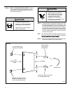
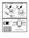
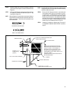
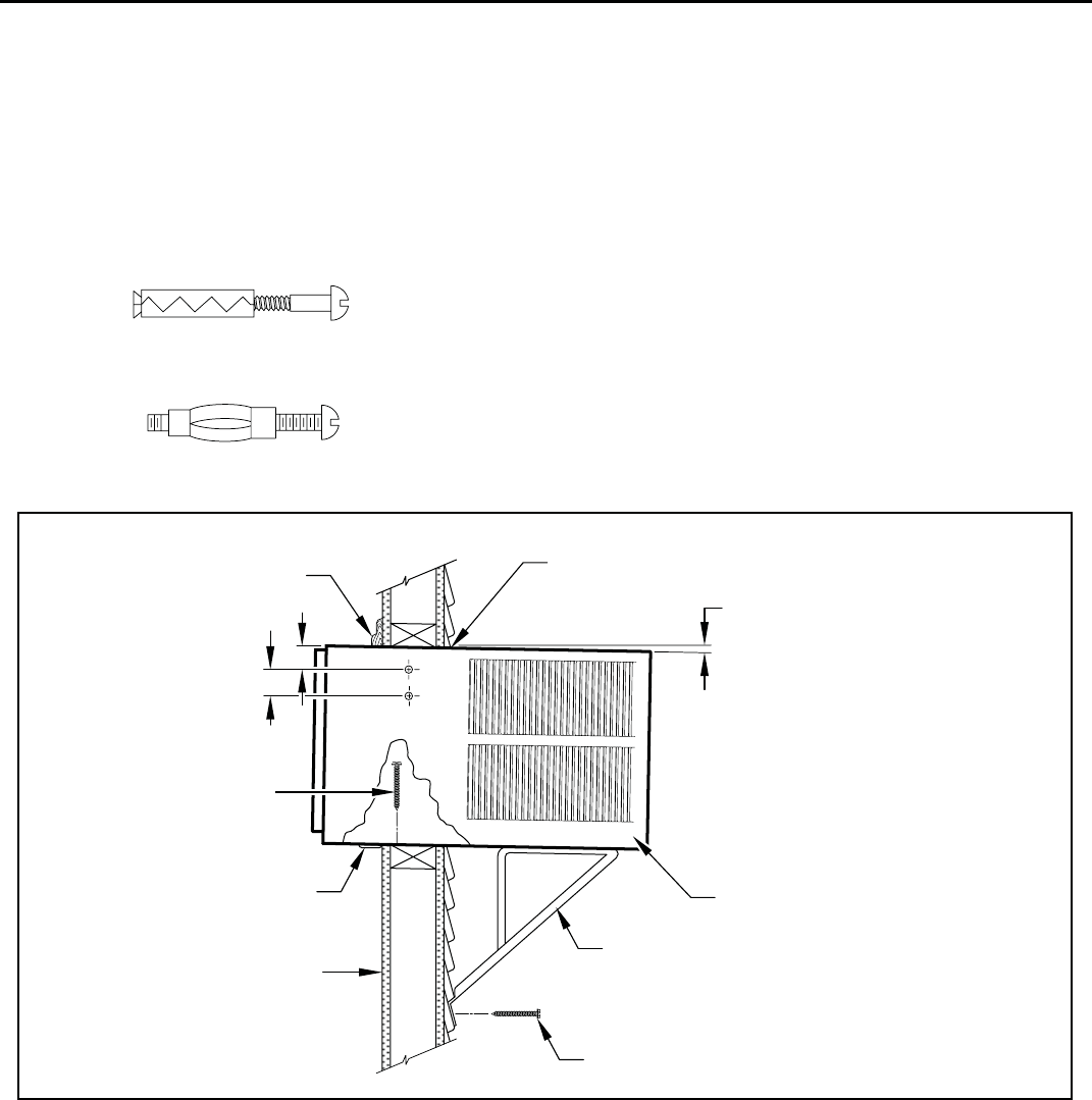
EXPANSION ANCHOR BOLT
MOLLY OR TOGGLE BOLT
FRR031
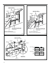
CAULK ALL SIDES WEATHER TIGHT
INSIDE AND OUTSIDE
3/8" SLOPE DOWN
NOTE: SUPPORT BRACKET MAY BE
OMITTED FROM THROUGH-THE-WALL
INSTALLATIONS IF THE CABINET IS
SECURED AS FOLLOWS. DRILL TWO
HOLES IN EACH SIDE AND INSTALL 4
FASTENERS (2 EACH SIDE). USE #12 x 2"
SCREWS, (ITEM 4).
TOGGLE BOLTS OR EXPANSION BOLTS
MAY BE REQUIRED.
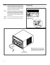
CABINET
SUPPORT BRACKETS
SCREW #12 x 2" LONG
DRILL 5/32" DIA. PILOT HOLES.
TRIM MOULDING
SCREW #12 x 2"
LONG (USE 3)
(ITEM 4)
SILL PLATE GUIDE CHANNEL
INSIDE WALL SURFACE
3"
4"
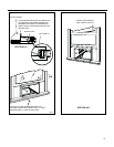
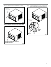
STEP 6. Slide the cabinet into the hole far enough to allow the
guide-channel of the sill plate to contact the inside wall surface
(Figure 21).
STEP 7. Drill three (3) 5/32” diameter pilot holes (use the sill-plate holes
as a guide) into the frame and install three (3) #12 x 2" long
screws (Item 4) (Figure 21).
NOTE: Alternate fasteners are required when securing the sill plate or
support brackets to material other than wo
od (cinder block, brick,
masonry or concrete). These items can be purchased at your
local hardware store.
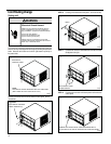
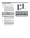
NOTE: DO NOT LEVEL the cabinet from front to back. Make sure there
is approximately 3/8” to 1/2” slope (1/8 to 1/4 bubble on the level)
toward the outside of the house.
STEP 8. Drill two (2) 5/32" diameter pilot holes in each cabinet side
at the locations shown (Figure 21) and install four (4) #12 x
2" screws (Item 4). P
rovided that Step 5 (hole construction)
provides a sturdy mount with solid vertical studs, support
brackets may not be required. The installation must support
the weight of the unit plus an additional weight of 400 pounds
on the rear of the cabinet. If support brackets (Item 1) are
available, they can be installed as shown in Figure 21.
STEP 9. Complete the installation by following steps 12 through 15
of “STANDARD WINDOW INST
ALLATION” instructions,
page 25.
Figure 44