


36
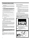
Through-the-Wall Installation
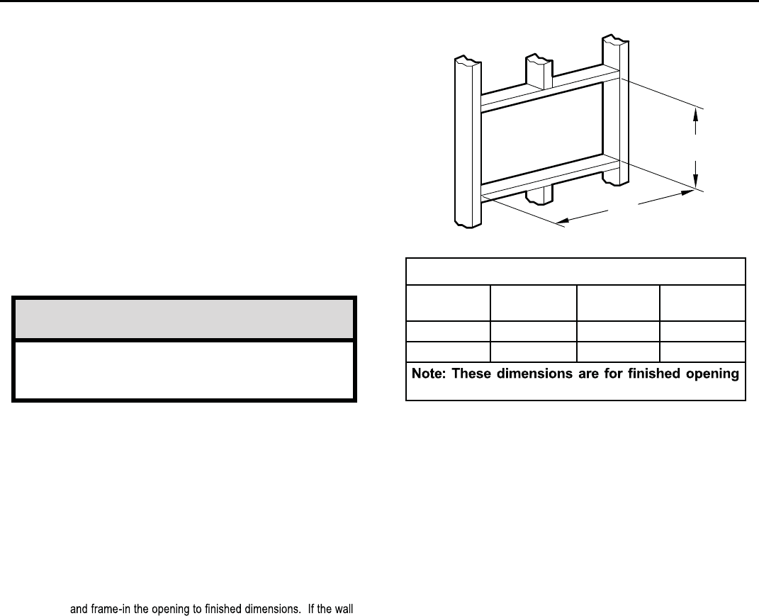
Table 3
FINISHED
DIMENSION
SMALL
CHASSIS
MEDIUM
CHASSIS
LARGE
CHASSIS
A 16
3
»16" 18
3
»16" 20
3
»8"
B 26
3
»
16
" 26
3
»
16
" 28
1
»
4
"
size.
B
A
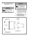
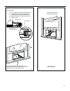
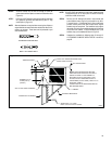
NOTICE
The outside cabinet condenser air intake louvers
MUST NOT BE BLOCKED by extra thick walls.
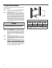
STEP 3. WALL PREPARATION – The maximum wall thickness
permissible without special construction is determined by
the model size to be installed. Observe the maximum wall
thickness shown in Figure 40. Walls exceeding the maximum
thickness shown in the chart, should be altered as shown in
Figure 40.
STEP 4. CHECKING WIRING AND PLUMBING – Check for wiring and
plumbing inside and outside of the wall to be sure none will be
damaged w
hen the cabinet framework is being constructed.
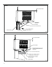
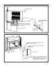
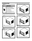
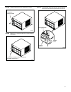
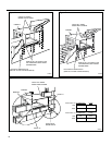
STEP 5. OPENING CONSTRUCTION – Depending upon size of unit
to be installed, lay out the hole dimensions per Table 3. Cut
construction is typical frame or 2” x 4” studding with brick or
For masonry, concrete or cinder block walls, locate opening
for your convenience (See Figures 41, 42, and 43).
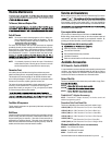
The following instructions apply to wood, masonry, brick, concrete or cinder
block wall construction.
STEP 1. Follow steps 1, 2, 3, and 4 of the "STANDARD WINDOW
INSTALLATION" instructions beginning on page 25.
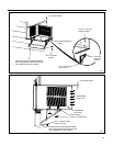
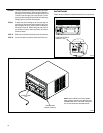
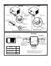
STEP 2. CABINET PREPARATION – Remove the sill
plate from the
Note that the chassis retainer is secured by a right side nut
and screw (Detail A, Figure 39). Bend the tabs of the sill plate
down into its channel at both ends of the plate or cut them off
(Detail B, Figure 39) Rotate the sill plate 180° (end-to-end,
Detail B, Figure 39) and reinstall. Reverse the orientation of
the nuts and screws, so that the head of the screws are on the
underside of cabinet facing up and the nuts are on top (Detail
C, Figure 39). Ensure that the chassis retainer is reinstalled
as shown in the detail.
cabinet by removing two (4) nuts and screws (Figure 39).
stone veneers, locate the opening next to one of the studs.