


9
NOTE: This procedure can be sped up by the
use of heat lamps, or by breaking the vacuum
with refrigerant or dry nitrogen at 5,000 microns.
Pressure system to 5 PSIG and leave in the sys-
tem a minimum of 10 minutes. Recover refriger-
ant, and proceed with evacuation to a pressure
of 200 microns or a minimum of 10%.
11. Break the vacuum by charging the system from
the high side with the correct amount of refrigerant
specifi ed. This will prevent boiling the oil out of the
crankcase.
NOTE: If the entire charge will not enter the high
side, allow the remainder to enter the low side
in small increments while operating the unit.
12. Restart the unit several times after allowing
pressures to stabilize. Pinch off the process tubes,
cut and solder the ends. Remove the pinch off tool,
and leak check the process tube ends.
SPECIAL PROCEDURES IN THE CASE OF
COMPRESSOR MOTOR BURNOUT
1. Recover all refrigerant and oil from the system.
2. Remove the compressor, capillary tube and fi lter
drier from the system.
3. Flush the evaporator, condenser and all connecting
tubing with dry nitrogen, or equivalent, to remove all
contamination from the system. Inspect the suction
and discharge lines for carbon deposits. Remove
and clean if necessary.
4. Reassemble the system, including a new drier-
strainer and capillary tube.
5. Proceed with processing as outlined under hermetic
component replacement.
HERMETIC COMPONENT REPLACEMENT
The following procedure applies when replacing
components in the sealed refrigeration circuit or
repairing refrigerant leaks. (Compressor, condenser,
evaporator, capillary tube, refrigerant leaks, etc.)
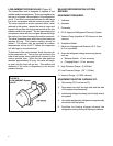
1. Recover the refrigerant from the system at the
process tube located on the high side of the system
by installing a line tap on the process tube. Apply
the gauge from the process tube to EPA approved
gauges from the process tube to the EPA approved
recovery system. Recover the CFC’s in the system
to at least 5%.
2. Cut the process tube below the pinch off in the
suction side of the compressor.
3. Connect the line from the nitrogen tank to the
suction process tube.
4. Drift dry nitrogen through the system and unsolder
the more distant connection fi rst. (Filter drier, high
side process tube, etc.)
5. Replace the inoperative component, and always
install a new fi lter drier. Drift dry nitrogen through
the system when making these connections.
6. Pressurize the system to 30 PSIG with proper
refrigerant and boost the refrigerant pressure to
150 PSIG with dry nitrogen.
7. Leak test the complete system with the electric
halogen leak detector, correcting any leaks
found.
8. Reduce the system to zero gauge pressure.
9. Connect the vacuum pump to the high side and
low side of the system with deep vacuum hoses,
or copper tubing. (Do not use regular hoses.)
10. Evacuate the system to an absolute holding
pressure of 200 microns or less.