


4
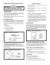
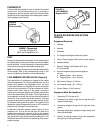
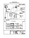
COMPRESSOR WINDING TEST (Figure 2.)
Remove the compressor terminal box cover and disconnect the
wires from the terminals. Using an ohmmeter, check continuity
across the following:
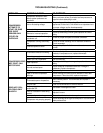
COMPONENT OPERATION AND TESTING
COMPRESSORS
Compressors are single phase, 208/230 volt. All compressor
motors are permanent split capacitor type, using only a running
capacitor across the start and run terminal.
All compressors are internally spring mounted and externally
mounted on rubber isolators.
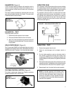
Line Voltage Overload
The compressor is equipped with an internal line voltage over-
load. This overload is embedded in the windings of the motor
to sense the motor temperature. The overload will open and
disconnect the power to the motor due to high temperatures
caused by:
1. A locked rotor.
2. Excessive running amps.
3. High discharge temperature.
4. Low refrigerant charge.
FIGURE 1 INTERNAL OVERLOAD
LINE BREAK
INTERNAL OVERLOAD
OHMMETER
FIGURE 2 COMPRESSOR WINDING TEST
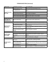
Testing Procedures
1. Terminal "C" and "S" – no continuity – open winding
– replace compressor.
2. Terminal "C" and "R" – no continuity – open winding
– replace compressor.
3. Terminal "R" and "S" – no continuity – open winding
- replace compressor.
4. Terminal "C" and the shell of the compressor – continuity
– grounded motor – replace compressor.
5. Should continuity exist between terminals "R" and "S",
but not between terminals "C" and "S" and "C" and "R",
the internal overload may be open. If the compressor is
extremely hot, allow it suffi cient time to cool. It may require
as long as one hour for the compressor to cool suffi ciently
for the internal overload to close.
CHECKING COMPRESSOR EFFICIENCY
The reason for compressor ineffi ciency is normally due to bro-
ken or damaged suction and/or discharge valves, reducing the
ability of the compressor to pump refrigerant gas.
This condition can be checked as follows:
1. Install a piercing valve on the suction and discharge or liquid
process tube.
2. Attach gages to the high and low sides of the system.
3. Start the system. Run a "cooling or heating performance test."
If test shows:
A. Below normal high side pressure.
B. Above normal low side pressure.
C. Low temperature difference across the coil.
The compressor valves are faulty - replace the compressor.
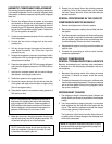
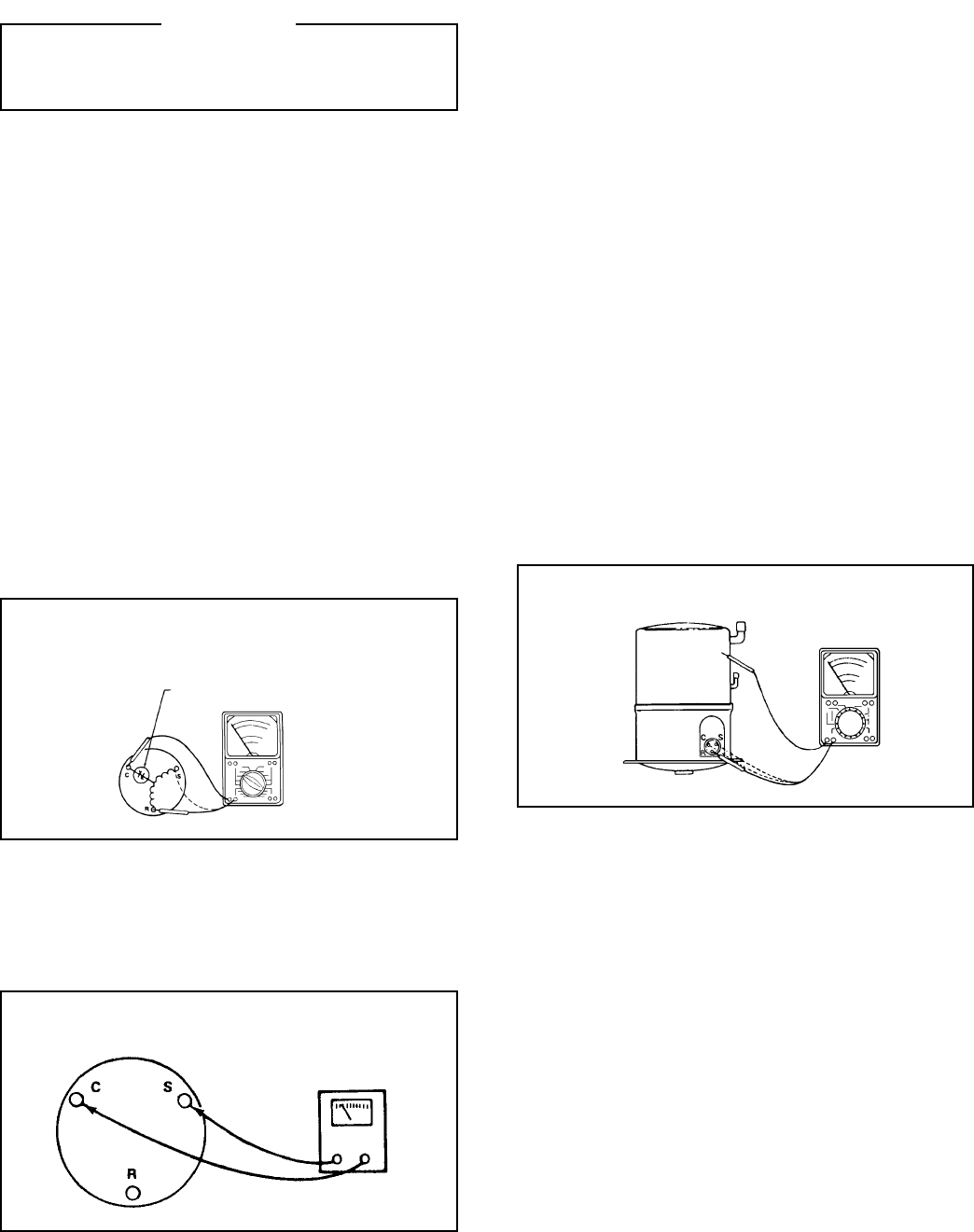
GROUND TEST
Use an ohmmeter set on its highest scale. Touch one lead to
the compressor body (clean point of contact, as a good connec-
tion is a must) and the other probe in turn to each compressor
terminal. (See Figure 3.) If a reading is obtained, the compressor
is grounded and must be replaced.
FIGURE 3 TYPICAL GROUND TEST
WARNING
DISCONNECT ELECTRICAL POWER TO THE
UNIT BEFORE SERVICING OR TESTING