


5
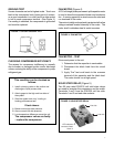
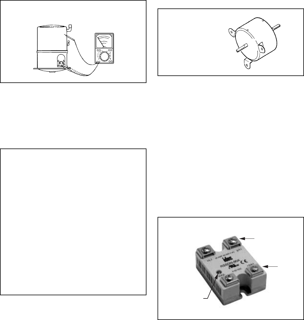
FAN MOTOR (Figure 4)
A 230 volt single phase permanent split capacitor motor
is used to drive the evaporator blower and condenser
fan. A running capacitor is wired across the start and
run terminals of the motor.
The motor is totally enclosed and is protected with a line
voltage overload located internally of the motor. The
motor shaft is stainless steel to resist corrosion.
CHECKING COMPRESSOR EFFICIENCY
The reason for compressor ineffi ciency is normally
due to broken or damaged suction and/or discharge
valves, reducing the ability of the compressor to pump
refrigerant gas.
This condition can be checked as
follows:
1. Install a piercing valve on the suction and
discharge or liquid process tube.
2. Attach gages to the high and low sides of
the system.
3. Start the system and run a "cooling or
heating performance test."
If test shows:
A. Below normal high side pressure.
B. Above normal low side pressure.
C. Low temperature difference across the coil.
The compressor valves are faulty
- replace the compressor.
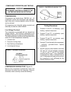
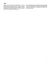
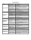
GROUND TEST
Use an ohmmeter set on its highest scale. Touch one
lead to the compressor body (clean point of contact,
as a good connection is a must) and the other probe
in turn to each compressor terminal. (See Figure 3.)
If a reading is obtained, the compressor is grounded
and must be replaced.
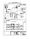
FIGURE 3 TYPICAL GROUND TEST
FAN MOTOR – TEST
Disconnect power to the unit.
1. Determine that the capacitor is serviceable.
2. Disconnect the black lead from the circuit
board.
3. Apply "live" test cord leads to the common
terminal of the capacitor and the black lead.
The motor should run at high speed.
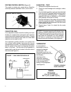
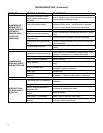
SOLID STATE RELAY (Figure 5)
Two 50 amp rated 208/230 volt solid state relays
are used to energize the compressor and fan motor.
Terminals 3 and 4 are the 208/230 volt line side.
Terminals 1 and 2 are load side contacts.
FIGURE 4 FAN MOTOR
FIGURE 5 SOLID STATE RELAY
LED indicates
contacts closed
when lit
Line side
Load side