


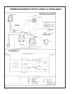
6
RED DOT
RUN CAPACITOR
FAN
MOTOR
COMPRESSOR
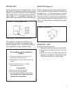
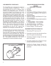
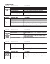
FIGURE 6 RUN CAPACITOR HOOK–UP
CAPACITOR, RUN
A run capacitor is wired across the auxiliary and
main winding of a single phase permanent split
capacitor motor such as the compressor and fan
motors. A single capacitor can be used for each
motor or a dual rated capacitor can be used for
both.
The capacitor’s primary function is to reduce the
line current while greatly improving the torque
characteristics of a motor. The capacitor also
reduces the line current to the motor by improving
the power factor of the load. The line side of the
capacitor is marked with a red dot and is wired to
the line side of the circuit. (See Figure 6.)
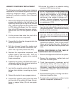
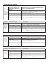
THERMOSTAT
A cross ambient
thermostat is used
to maintain the desired
comfort level. The
thermostat reacts only to
a change in temperature
at the bulb location.
Important to the
successful operation
of the unit is the position
of the sensing bulb in
relation to the evaporator.
See Figure 7.
FIGURE 7
SENSING BULB
LOCATION
CAPACITOR – TEST
1. Remove the capacitor from the unit.
2. Check for visual damage such as bulges,
cracks, or leaks.
3. For dual rated capacitors, apply an ohmmeter
lead to the common (C) terminal and the other
probe to the compressor (HERM) terminal.
A satisfactory capacitor will cause a deflection
on the pointer, then gradually move back to
infinity.
4. Reverse the leads of the probe and
momentarily touch the capacitor terminals.
The deflection of the pointer should be two
times that of the first check if the capacitor is
good.
5. Repeat steps 3 and 4 to check the fan motor
capacitor.
NOTE: A shorted capacitor will indicate a low
resistance and the pointer will move more
to the “0” end of the scale and remain there
as long as the probes are connected. An
open capacitor will show no movement of
the pointer when placed across the terminals
of the capacitor.
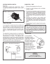
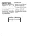
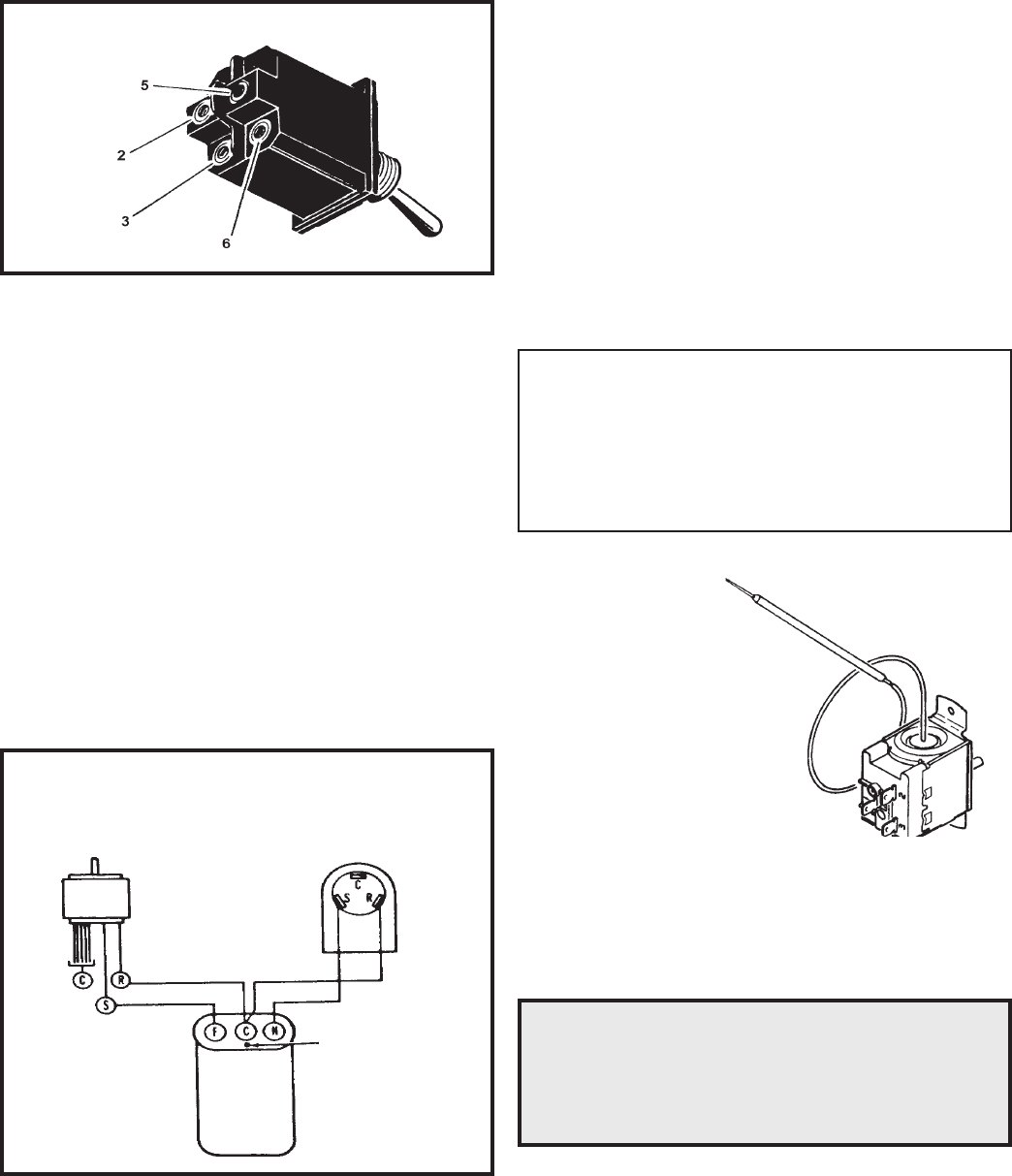
SYSTEM CONTROL SWITCH
(Figure 5)
This switch is double pole, single throw. Check
for continuity between terminals 2 and 3, and 5
and 6.
FIGURE 5 SWITCH, ON-OFF
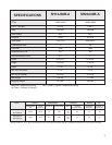
RANGE:
Thermostat
(Part No. 618-225-02)
60° F ( ± 2° ) to 90° F( ± 4° )