


2
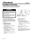
5. Drill two 3/16-in. mounting holes in wall where marked.
(Note: Mounting holes on back plate are designed to fi t on a
horizontal J-box).
6. Secure back plate to wall with 2 anchors and screws provid-
ed making sure all wires extend through hole in back plate.
7. Connect wires to proper terminal of the connector block
8. Push any excess wire back into wall. Excess wire inside
the thermostat plastic case can interfere with proper air fl ow
across the temperature sensor. Seal hole in wall to prevent
air leaks. Leaks can affect operation.
9. Install thermostat on back plate.
10. Turn on power to the unit.
On initial power up, the LCD readout will display
o
P
.
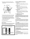
WIRING DIAGRAMS
NOTE: All excess wire should be pushed back into the wall as far
as possible. Excess wire inside the thermostat plastic case may
interfere with the air fl ow across the temperature sensor.
III CHECK THERMOSTAT OPERATION
1. Fan Operation
A. Press fan button, starting fan operation. Fan icon turns
on.
B. Press Fan button, stopping fan operation. Fan icon turns
off.
2. Heating Operation
A. Press and Release MODE button until HEAT is dis-
played.
B. Press up button until LCD readout reads 10 degrees
above room temperature. Heating system should begin
to operate within 5 minutes.
3. Cooling Operation
A. Press and Release MODE button until COOL is dis-
played
B. Press down button until LCD readout reads 10 degrees
below room temperature. Cooling system should begin
to operate within 5 minutes.
IV. THERMOSTAT OPERATION
1. TEMPERATURE DISPLAY
The thermostat will display room temperature until the UP or DOWN
button is pressed. The word SET appears when these buttons
are pressed and the current set point is displayed. If no buttons
are pressed for 5 seconds, the display will change back to show
room temperature.
2. TIMEGUARD TIMER
A 5-minute timeguard is built into the thermostat immediately upon
power up, and any time the compressor turns off. The compres-
sor will not turn on until the timeguard has expired. Pressing UP
and FAN buttons simultaneously will override the timeguard for
1 cycle.
3. CYCLE TIMER
In normal heating and cooling operation the thermostat will not
allow more than 4 equipment cycles per hour (or 1 cycle every
15 minutes). Both the Y and W outputs have a 15-minute timer
that starts counting down when the output is turned on, (e.g., if Y
output is turned on for 9 minutes and then satisfi es, it cannot turn
back on for another 6 minutes regardless of demand). However,
pressing UP and FAN buttons simultaneously or changing the set
point will override the timer for 1 cycle.
4. MINIMUM ON TIMER
Once the equipment has turned on, it will remain on for a minimum
of 3 minutes regardless of demand. However, the equipment can
turn off in less than 3 minutes if a change in set point, or a change
in mode occurs.
5. ERROR MESSAGES
E4 will be displayed if the thermostat has an internal memory failure.
If E4 appears, replace the thermostat.
- - (two dashes) will be displayed if the temperature cannot
properly read the room temperature. If - - appears, replace the
thermostat.
Y
G
R
C
HEAT
FAN
24 VAC HOT
2
4 VAC COMM
COOL
W
SINGLE STAGE HEAT/COOL WIRING
Unit Terminal Strip
B
W
C
R
Reversing Valve
Y
G
Thermostat
B
Connection to “B”
terminal required on
Heat Pump models
2.375
3.275
2.625
1.587