*
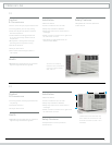
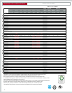
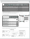
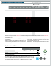
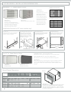
Minimum extensions when mounted in a window.
** Minimum widths achieved using one side curtain assembly as opposed to both in a standard installation.
† Sleeve P1 does not have thru-the-wall hole dimensions, as these units are xed chassis and should not be installed thru-the-wall.
NOTE: S,M and L sleeves may be installed in window with no side kits if properly installed.
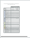
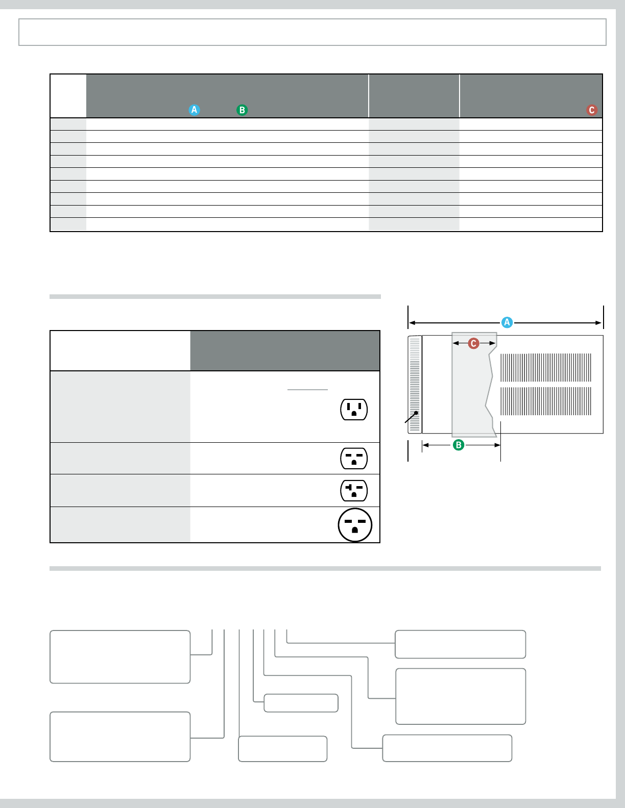
Circuit Rating/ Breaker
Model
Circuit Rating
Breaker or
T-D Fuse
Plug
Face
(NEMA#)
Power Cord
Length (ft.)
Wall Outlet
Appearance
(B)
(C)
Front
SIDE VIEW
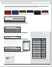
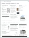
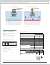
Room Air Conditioner Model Identification Guide
S L 28 M 3 0 A
FUNCTION
S–Straight Cool C–Straight Cool
X–Straight Cool Y–Heat Pump
E–Electric Heat
CHASSIS
Q–Portable P–Programmable
S–Small Chassis M–Medium Chassis
L–Large Chassis
MODEL SERIES
APPROXIMATE
Btu (000) Cooling
VOLTAGE
1–115 Volts 3–230/208 Volts
0 – Straight Cool and
115V Heat Pump Models
1 – 1 KW heat strip, Nominal
3 – 3 KW heat strip, Nominal
4 – 4 KW heat strip, Nominal
5 – 5 KW heat strip, Nominal
Letter at end of model number indicates
a modification to an existing model.
Sleeve Height Width
Depth
with Front
Shell Depth to
Louvers
Minimum
Extension
Into Room*
Minimum
Extension
Outside*
Window Width
Thru-the-wall Installation
Finished Hole
Minimum** Maximum Height Width Max. Depth
Q
P1†
P4
P5
P6
P7
S
M
L


