


32
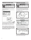
ELECTRIC SHOCK HAZARD
WARNING
Disconnect power to the unit before
servicing. Failure to follow this warning
could result in serious injury or death.
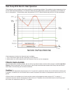
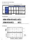
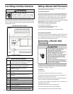
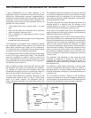
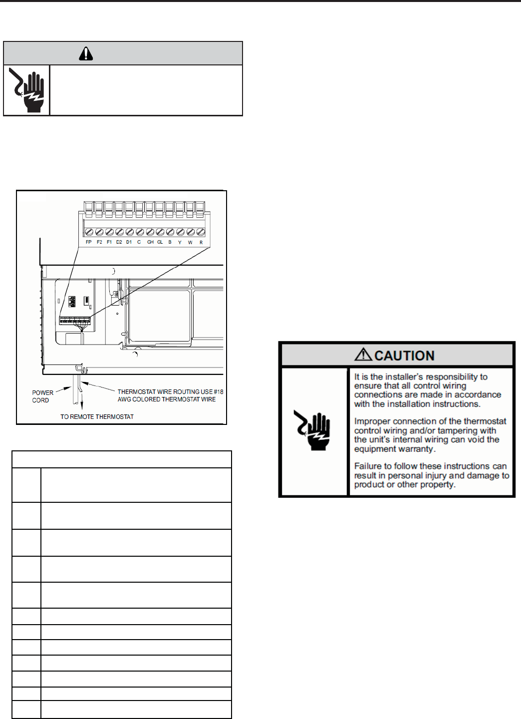
Low Voltage Interface Connector
All Kuhl and Kuhl + units have a low voltage interface connector through
which a Remote Wall Thermostat, Desk Control and Auxiliary Fan’s Relay
can be connected. The interface connector is located on the left side behind
the decorative front cover.
Interface Connector Definitions
Interface Connector Location
Table 1
FP
F2
F1
D2
D1
C
GH
GL
B
Y
W
R
Front Panel. Wire jumper between FP and
F2 enables front panel operation. Jumper off
enables remote wall t-stat operation.
Used with F1 to provide 24 VAC to external
fan relay. (See above for use with FP)
Used with F2 to provide 24 VAC to
external fan relay.
Used with D1 for desk control on or off
operation.
Used with D2 for desk control on or off
operation.
Common Ground Terminal
Call for high fan
Call for low fan
Call for compressor
Call for heating
24V Power from Electronic Control to Wall
Call for heat pump reversing valve
Figure 1
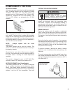
Adding a Remote Wall Thermostat
An external thermostat may be added to the air conditioner to provide
remote temperature sensing and control.
Thermostat Selection
Friedrich recommends the use of either the Friedrich RT4 or RT5. These
thermostats are single stage heat/cool, manual changeover. The RT4 is a
digital display thermostat with single speed fan control. The RT5 features
a digital display, two fan speed selection, fi lter check light, temperature
limiting, status indicator light, room temperature offset, backlight and
battery backup. Other thermostats may be used as long as they are single
stage heat/cool and are confi gured correctly for the unit.
Thermostat terminals requirements:
For cooling only units: C, R, G, Y.
For cooling with electric heat units: C, R, G, Y, W.
For heat pump units: C, R, G, Y, W, B.
For two fan speeds, thermostat must have 2 fan speed selection.
During Heat Pump Mode:
The B terminal must be continuously energized. The W terminal must have
24 VAC output to call for heat. The control board decides on whether to
turn on the Heat Pump Heat (compressor) or Electric Heat. The Y terminal
should not have 24 VAC output during heat mode.
To enable the remote thermostat operation, remove the jumper between
terminals FP & F2 on the interface connector. Connect the thermostat
using Figure 1 and Table 1 as a guide.
Procedure
1) Unplug the unit.
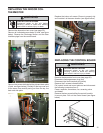
2) Unscrew and remove the decorative front cover. (Page 30)
3) Locate the Interface Connector (24 VAC terminal strip (See fi gure 1 at
left) and remove the jumper wire at FP and F2.
4) Make the wire connections according to the confi guration needed for
your unit (see above or page 68 for wiring diagrams).
5) Once each wire is matched and connected, the unit is now ready to be
controlled by the thermostat.
6) Reattach the decorative front cover (see page 30).
Note: Under T-Stat operation the front panel is disabled
except the Maintenance functions (see page 29 for details).
Connecting a Remote Wall
Thermostat