


En-3
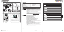
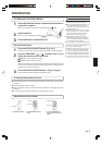
NAME OF PARTS
● Refer to the folded out page on the cover.
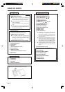
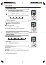
Fig. 6 Remote Control Unit
I SLEEP button
J MASTER CONTROL button
K SET TEMP. button (
/ )
L Signal Transmitter
M TIMER MODE button
N TIMER SET (
/ ) button
O FAN CONTROL button
P START/STOP button
Q SET button (Vertical)
R SET button (Horizontal)
S SWING button
T RESET button
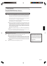
U TEST RUN button
● This button is used when installing the
conditioner, and should not be used un-
der normal conditions, as it will cause the
air conditioner’s thermostat function to op-
erate incorrectly.
● If this button is pressed during normal op-
eration, the unit will switch to test opera-
tion mode, and the Indoor Unit’s OPERA-
TION Indicator Lamp and TIMER Indicator
Lamp will begin to flash simultaneously.
● To stop the test operation mode, press the
START/STOP button to stop the air condi-
tioner.
V CLOCK ADJUST button
W Remote Control Unit Display (Fig. 7)
X Transmit Indicator
Y Clock Display
Z Operating Mode Display
[ Timer Mode Display
\ Fan Speed Display
] Temperature SET Display
` SLEEP Display
a SWING Display
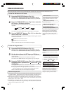
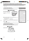
Fig. 1 Indoor Unit
1 Operating Control Panel (Fig. 2)
2 MANUAL AUTO button
●
When kept on pressing the MANUAL
AUTO button for more than 10 seconds,
the forced cooling operation will start.
● The forced cooling operation is used at the
time of installation.
Only for authorized service personnel's
use.
● When the forced cooling operation starts
by any chance, press the START/STOP but-
ton to stop the operation.
3 Indicator (Fig. 3)
4 Remote Control Signal Receiver
5 OPERATION Indicator Lamp (red)
6 TIMER Indicator Lamp (green)
●
If the TIMER indicator lamp flashes when
the timer is operating, it indicates that a
fault has occurred with the timer setting
(See Page 13 Auto Restart).
7 SUPER QUIET Indicator Lamp (orange)
8 Intake Grille (Fig. 4)
9 Front Panel
0 Air Filter
A Air Flow Direction Louver
B Power Diffuser
C Right-Left Louver
(behind Air Flow Direction Louver)
D Drain Hose
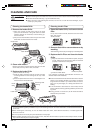
Fig. 5 Outdoor Unit
E Intake Port
F Outlet Port
G Pipe Unit
H Drain port (bottom)