


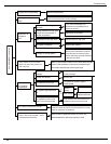
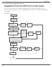
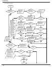
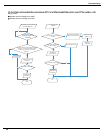
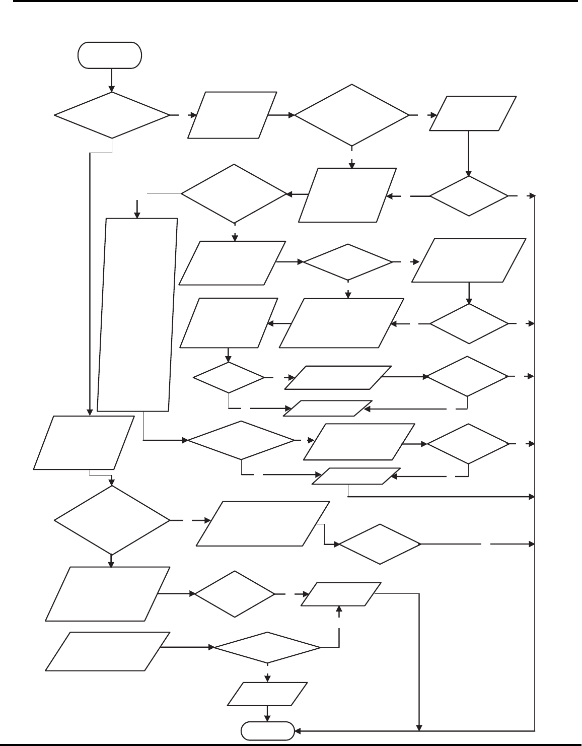
Troubleshooting
Energize and
switch on
IPM protection
occurs after the
machine has run for
a
p
eriod of time?
Use AC voltmeter
to measure the
voltage between
terminal L and N
on the wiring
board XT)
If the voltage
between terminal L
and N on wiring
board XT is within
210VAC~250VAC?
Check the supply
voltage and
restore it to
210VAC~250VAC
Voltage between
the two ends of
electrolytic
capacitor (test3) is
hi
g
her than 250V
Start and run the
unit. Before
protection occurs,
use DC voltmeter to
measure the voltage
between the two
ends of electrolytic
capacitor on control
p
anel AP1
(
test3
)
If the unit can
work
normally?
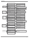
Please confirm:
1. If the indoor and
outdoor heat
exchangers are
dirty? If they are
obstructed by other
objects which affect
the heat exchange
of indoor and
outdoor unit.
2. If the indoor and
outdoor fans are
working normally?
3. If the environment
temperature is too
high, resulting in
that the system
pressure is too high
and exceeds the
permissible range?
4. If the charge
volume of
refrigerant is too
much, resulting in
that the system
pressure is too
high?
5. Other conditions
resulting in that the
system pressure
becomes too high.
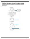
The connection
of capacitor C2
is loose.
Stop the unit and
disconnect the powe
r
supply. Then, check
the connection o
f
capacitor C2
according to Electrical
Wiring Diagram.
Reconnect the
capacitor C2 according
to Electrical Wiring
Diagram. Then,
energize and start the
unit.
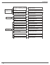
Remove the wires
on the two ends o
f
capacitor C2. Then,
use capacitance
meter to measure
the capacitor C2.
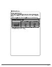
Verify as per the
Parameters Sheet.
Stop the unit and
disconnect the power
supply. Wait 20 minutes,
or use DC voltmeter to
measure the voltage
between the two ends of
capacitor C2, until the
voltage is lower than 20V
If capacito
r
C2 is failed?
Replace the capacitor
C2. Then, energize
and start the unit.
Replace the
control panel AP1
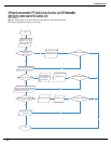
Take corrective actions
according to Technical
Service Manual, and
then energize and start
the unit.
If there is any
abnormality
described above?
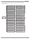
Refer to the
Electrical Wiring
Diagram and check
if the connection
between AP1 and
COMP is loose and i
f
the connection order
is correct.
Replace the
control panel AP1
If the connection
between AP1 and
COMP is unsecure
or the connection
order is wrong?
Connect the control panel
A
P1 and compressor
COMP correctly according
to the Electrical Wiring
Diagram. Then, energize
and start the unit.
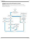
Use ohmmeter to
measure the resistance
between the three
terminals on compressor
COMP, and compare the
measurements with the
compressor resistance on
Service Manual.
If the
resistance is
normal?
Use ohmmeter to
measure the resistance
between the two
terminals of compressor
COMP and copper tube.
Replace the
compressor
COMP
Resistance higher
than 500MΩ?
Replace the
control panel
AP1
END
Y N
Y
N
Y
N
Y
If the unit can
work
normall
y
?
Y
If the unit can
work
normally?
Y
N
N
Y
N
If the unit can
work
normally?
Y
Y
N
N
If the unit can
work
normally?
Y
Y
N
N
N
N
Y
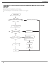
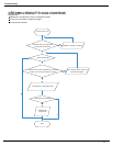
Fault diagnosis process:
54