


Page 13
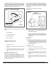
a. Balance Scales - 1/2 oz. accuracy
b. Charging Board - 1/2 oz. accuracy
9. High Pressure Gauge - (0 - 400 lbs.)
10. Low Pressure Gauge - (30 - 150 lbs.)
11. Vacuum Gauge - (0 - 1000 microns)
EQUIPMENT MUST BE CAPABLE OF:
1. Recovering CFCs as low as 5%.
2. Evacuation from both the high side and low side of
the system simultaneously.
3. Introducing refrigerant charge into high side of the
system.
4. Accurately weighing the refrigerant charge actually
introduced into the system.
5. Facilities for flowing nitrogen through refrigeration
tubing during all brazing processes.
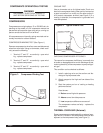
HERMETIC COMPONENT REPLACEMENT
The following procedure applies when replacing compo-
nents in the sealed refrigeration circuit or repairing re-
frigerant leaks. (Compressor, condenser, evaporator, cap-
illary tube, refrigerant leaks, etc.)
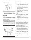
1. Recover the refrigerant from the system at the pro-
cess tube located on the high side of the system by
installing a line tap on the process tube. Apply gauge
from process tube to EPA approved gauges from
process tube to EPA approved recovery system.
Recover CFCs in system to at least 5%.
2. Cut the process tube below pinch off on the suc-
tion side of the compressor.
3. Connect the line from the nitrogen tank to the suc-
tion process tube.
4. Drift dry nitrogen through the system and unsolder
the more distant connection first. (Filter drier, high
side process tube, etc.)
5. Replace inoperative component, and always install
a new filter drier. Drift dry nitrogen through the sys-
tem when making these connections.
6. Pressurize system to 30 PSIG with proper refriger-
ant and boost refrigerant pressure to 150 PSIG with
dry nitrogen.
7. Leak test complete system with electric halogen
leak detector, correcting any leaks found.
8. Reduce the system to zero gauge pressure.
9. Connect vacuum pump to high side and low side
of system with deep vacuum hoses, or copper
tubing. (Do not use regular hoses.)
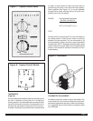
10. Evacuate system to maximum absolute holding
pressure of 200 microns or less. NOTE: This pro-
cess can be speeded up by use of heat lamps, or
by breaking the vacuum with refrigerant or dry
nitrogen at 5,000 microns. Pressure system to 5
PSIG and leave in system a minimum of 10 min-
utes. Recover refrigerant, and proceed with evacu-
ation of a pressure of 200 microns or a minimum
of 10 %.
11. Break vacuum by charging system from the high
side with the correct amount of refrigerant speci-
fied. This will prevent boiling the oil out of the crank-
case.
NOTE: If the entire charge will not enter the high
side, allow the remainder to enter the low side in
small increments while operating the unit.
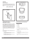
12. Restart unit several times after allowing pressures
to stabilize. Pinch off process tubes, cut and sol-
der the ends. Remove pinch off tool, and leak
check the process tube ends.
SPECIAL PROCEDURE IN THE CASE OF
MOTOR COMPRESSOR BURNOUT
1. Recover all refrigerant and oil from the system.
2. Remove compressor, capillary tube and filter drier
from the system.
3. Flush evaporator condenser and all connecting
tubing with dry nitrogen or equivalent, to remove
all contamination from system. Inspect suction and
discharge line for carbon deposits. Remove and
clean if necessary.
4. Reassemble the system, including new drier
strainer and capillary tube.
5. Proceed with processing as outlined under her-
metic component replacement.