


Page 10
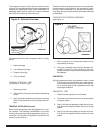
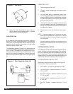
Figure 5: Fan Motor
5. Apply “live” test cord probes on each of the re-
maining wires from the speed switch or system
switch to test intermediate speeds.
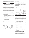
CAPACITOR, RUN
A run capacitor is wired across the auxiliary and main
winding of a single phase permanent split capacitor
motor such as the compressor and fan motor. A single
capacitor can be used for each motor or a dual rated
capacitor can be used for both.
The capacitor’s primary function is to reduce the line
current while greatly improving the torque characteris-
tics of a motor. The capacitor also reduces the line cur-
rent to the motor by improving the power factor of the
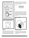
load. The line side of the capacitor is marked with a red
dot and is wired to the line side of the circuit (see Figure
6.)
Figure 6: Run Capacitor Hook-Up
CAPACITOR - TEST
1. Remove capacitor from unit.
2. Check for visual damage such as bulges, cracks,
or leaks.
3. For dual rated, apply an ohmmeter lead to com-
mon (C) terminal and the other probe to the com-
pressor (HERM) terminal. A satisfactory capacitor
will cause a deflection on the pointer, then gradu-
ally move back to infinity.
4. Reverse the leads of the probe and momentarily
touch the capacitor terminals. The deflection of the
pointer should be two times that of the first check if
the capacitor is good.
5. Repeat steps 3 and 4 to check fan motor capaci-
tor.
NOTE: A shorted capacitor will indicate a low resis-
tance and the pointer will move to the “0” end of
the scale and remain there as long as the probes
are connected.
An open capacitor will show no movement of the
pointer when placed across the terminals of the
capacitor.
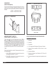
SYSTEM CONTROL SWITCH
A five position control switch is used to regulate the op-
eration of the fan motor and compressor. The compres-
sor can be operated with the fan operating at low, me-
dium or high speed. The fan motor can also be operated
independently on medium speed. See switch section as
indicated on decorative control panel (see Figure 7.)
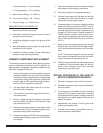
SYSTEM CONTROL SWITCH - TEST
Disconnect leads from control switch (see Figure 8.)
There must be continuity as follows:
1. “Off” Position - no continuity between terminals.
2. “Lo Cool” Position - between terminals “L1” and “C”,
“LO” and “MS”.
3. “Med Cool” Position - between terminals “L1” and
“C”, “M” and “MS”.
4. “Hi Cool” Position - between terminals “L1” and “C”,
“H” and “MS”.
5. “Fan Only” Position - between terminals “L1” and
“2”.