


The Vert-I-Pak A series units must be installed with a free
return air configuration. The table below lists the indoor
airflow at corresponding static pressures. All units are rarted
at low speed.
The Vert-I-Pak units are designed for either single speed or
two fan speed operation. For single speed operation refer to
the airflow table below and select the most appropriate CFM
based on the ESP level. Connect the fan output from the
thermostat to the unit on either the GL terminal for low speed
or to the GH terminal for high speed operation.
For thermostats with two-speed fan outputs connect the low
speed output to the unit GL terminal and the high speed
output to the GH terminal.
Ductwork Preparation
Indoor Airflow Data
Fresh Air Door
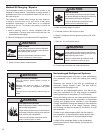
If flex duct is used, be sure all the slack is pulled out of the
flex duct. Flex duct ESP can increase considerably when
not fully extended. DO NOT EXCEED a total of .30 ESP, as
this is the MAXIMUM design limit for the VERT-I-PAK
A-Series unit.
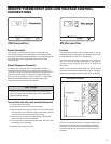
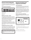
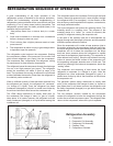
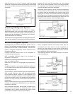
The Fresh Air Door is an “intake” system. The fresh air door
opened via a slide on the front of the chassis located just
above the indoor coil. Move the slide left to open and right
to close the fresh air door. The system is capable of up to 60
CFM of fresh air @ ~.3” H20 internal static pressure.
IMPORTANT: FLEX DUCT CAN COLLAPSE AND
CAUSE AIRFLOW RESTRICTIONS. DO NOT
USE FLEX DUCT FOR: 90 DEGREE BENDS, OR
UNSUPPORTED RUNS OF 5 FT. OR MORE.
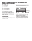
EXAMPLE: Measured voltage to unit (heaters) is 230 volts.
Measured Current Draw of strip heaters is 11.0 amps.
230 x 11.0 = 2530
2530/1000 = 2.53 Kilowatts
2.53 x 3413 = 8635
Supply Air 95
°
F
Return Air 75
°
F
Temperature Rise 20
°
20 x 1.08 = 21.6
8635
= 400 CFM
21.6
1 ½ TON SYSTEM ( 18,000 Btu)
Operating on high speed @ 230 volts with dry coil
measured external static pressure .10
Air Flow = 450 CFM
In the same SYSTEM used in the previous example but
having a WET coil you must use a correction factor of
.95 (i.e. 450 x .95=428 CFM) to allow for the resistance
(internal) of the condensate on the coil.
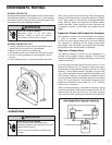
It is important to use the proper procedure to check
external
Static Pressure and determine actual airfl ow. Since in
the case of the VERT-I-PAK, the condensate will cause
a reduction in measured External Static Pressure for the
given airfl ow.
It is also important to remember that when dealing with
VERT-l-PAK units that the measured External Static
Pressure increases as the resistance is added externally
to the cabinet. Example: duct work, fi lters, grilles.
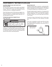
Checking Approximate Airfl ow
If an inclined manometer or Magnehelic gauge is not
available to check the External Static Pressure, or the
blower performance data is unavailable for your unit,
approximate air fl ow call be calculated by measuring the
temperature rise, then using tile following criteria.
KILOWATTS x 3413
= CFM
Temp Rise x 1.08
Electric Heat Strips
The approximate CFM actually being delivered can be
calculated by using the following formula:
DO NOT simply use the Kilowatt Rating of the heater (i.e.
2.5, 3.4, 5.0) as this will result in a less-than-correct airfl ow
calculation. Kilowatts may be calculated by multiplying
the measured voltage to the unit (heater) times the
measured current draw of all heaters (ONLY) in operation
to obtain watts. Kilowatts are than obtained by dividing
by 1000.
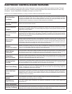
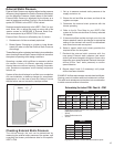
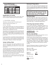
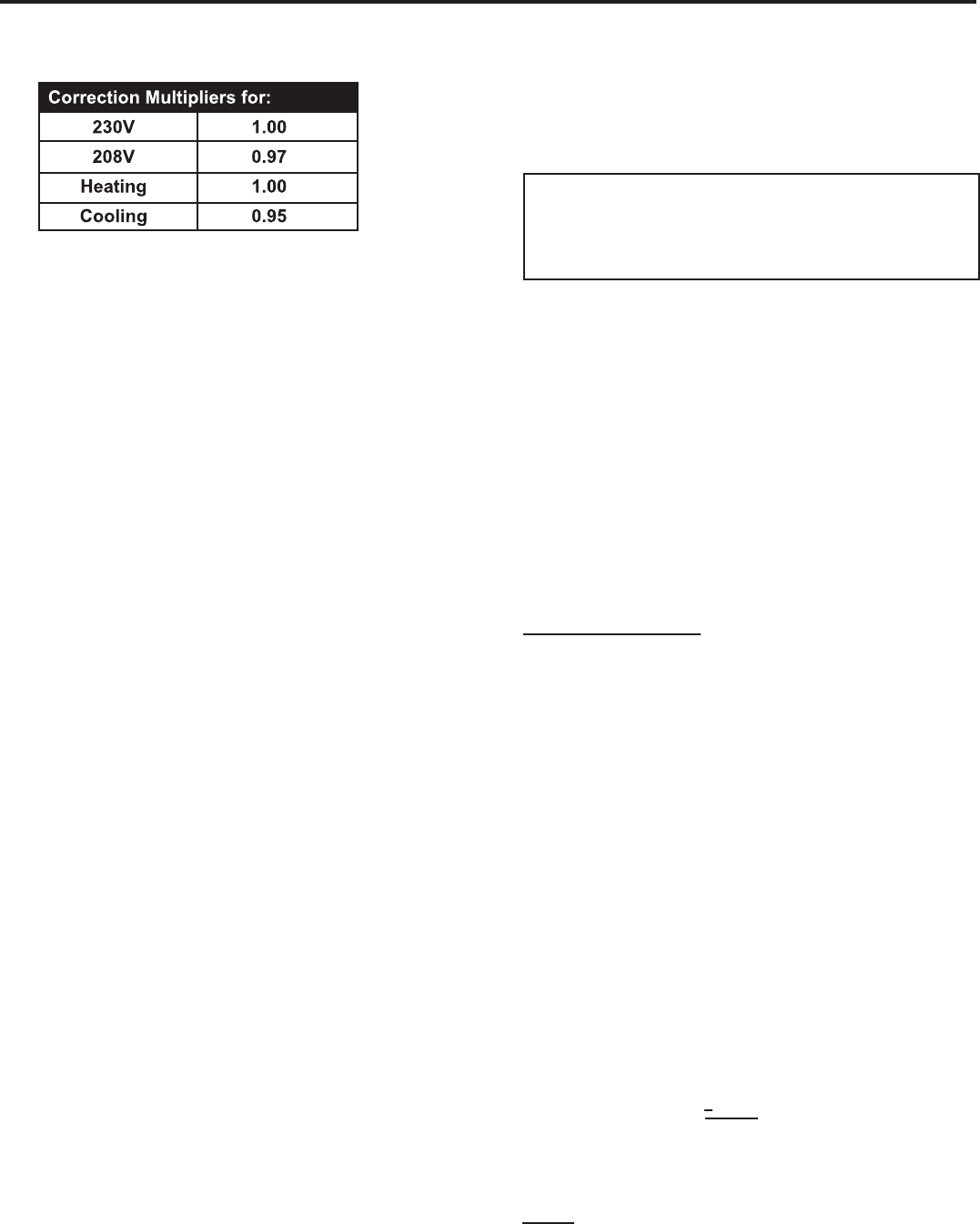
Explanation of charts
Chart A is the nominal dry coil VERT-I-PAK CFMs. Chart
B is the correction factors beyond nominal conditions.
Correct CFM (if needed):
Chart B – Correction Multipli
ers
16