


—2—
1. PREFACE
1.1 SAFETY PRECAUTIONS................................2
1.2 INSULATION RESISTANCE TEST.................2
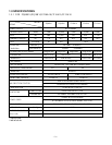
1.3 SPECIFICATIONS...........................................3
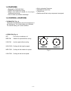
1.4 FEATURES......................................................4
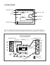
1.5 CONTROL LOCATIONS .................................4
2.
DISASSEMBLY INSTRUCTIONS
2.1 MECHANICAL PARTS ....................................6
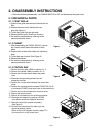
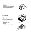
2.1.1 FRONT GRILLE .....................................6
2.1.2 CABINET................................................6
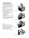
2.1.3 CONTROL BOX .....................................6
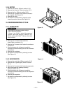
2.2 AIR HANDLING PARTS ..................................7
2.2.1 AIR GUIDE AND TURBO FAN...............7
2.2.2 FAN ........................................................7
2.2.3 SHROUD................................................8
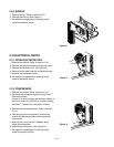
2.3 ELECTRICAL PARTS......................................8
2.3.1 OVERLOAD PROTECTOR....................8
2.3.2 COMPRESSOR......................................8
2.3.3 CAPACITOR...........................................9
2.3.4 POWER CORD ......................................9
2.3.5 MOTOR ................................................10
2.4 REFRIGERATION CYCLE ............................10
2.4.1 CONDENSER.......................................10
2.4.2 EVAPORATOR.....................................10
2.4.3 CAPILLARY TUBE ...............................11
3. TROUBLESHOOTING GUIDE
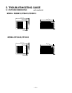
3.1 OUTSIDE DIMENSIONS...............................13
3.2 PIPING SYSTEM...........................................14
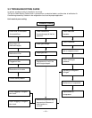
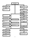
3.3 TROUBLESHOOTING GUIDE .....................15
1. PREFACE
This
SERVICE MANUAL provides various service information, including the mechanical and electrical
parts etc. This room air conditioner was manufactured and assembled under a strict quality control system.
The refrigerant is charged at the factory. Be sure to read the safety precautions prior to servicing the unit.
CONTENTS
.
.
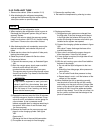
1.1 SAFETY PRECAUTIONS
1. When servicing, turn the unit Off and unplug the
power cord.
2. Observe the original lead dress.
If a short circuit is found, replace all parts which have
been overheated or damaged by the short circuit.
3. After servicing, make an insulation resistance test to
prevent the customer from being exposed to shock
hazards.
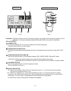
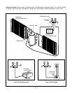
1.2
INSULATION RESISTANCE TEST
1. Unplug the power cord and connect a jumper between 2 pins
(black and white).
2. The grounding conductor (green or green and yellow) is to be
open.
3. Measure the resistance value with an ohm meter between the
jumpered lead and each exposed metallic part on the equip-
ment at each working status.
4. The value should be over 1 MΩ.
5. EXPLODED VIEW ..................................20
6. REPLACEMENT PARTS LIST........21
4. SCHEMATIC DIAGRAM.....................19