22
COMPONENTS TESTING (Continued)
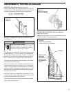
DEFROST THERMOSTAT (Heat Pump Models Only)
(See Figure 21)
This thermostat is single pole - double throw with contacts
between terminals “2” and “3” closing on temperature rise
and contacts between terminals “2” and “1” closing on
temperature fall. When the contacts between terminals “2”
and “1” make, power is supplied to the heater element.
This control is dual purpose control that acts as an outdoor
thermostat and defrost control.
When the sensing bulb, attached to the outdoor coil,
senses enough icing on the outdoor coil, it will interrupt
power to the compressor and supply power to the heating
element until the coil temperature reaches above 43°, then
the heater will shut off and the unit will resume operating in
the reverse cycle mode.
When the outdoor coil temperature drops below 20°, the
unit will operate in electric heat mode continuously until the
outdoor coil temperature rises above 43°.
The fan motor will not turn off when defrost occurs, and the
4-way valve will not reverse.
Figure 21
Defrost Thermostat
(Heat Pump Models)
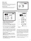
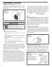
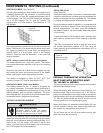
DEFROST BULB LOCATION (Heat Pump Models
Only) (See Figure 22)
The defrost control bulb must be mounted securely and in
the correct location to operate properly.
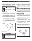
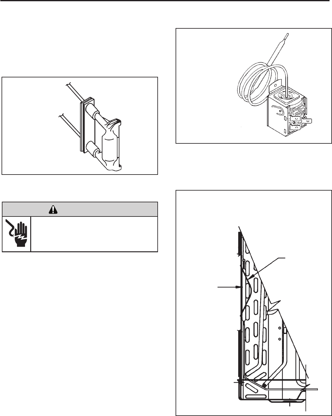
RESISTOR: Heat Anticipator (See Figure 20)
Failure of the resistor will cause prolonged “off” and “on”
cycles of the unit. When replacing a resistor, be sure and use
the exact replacement. Resistor ratings are as follows:
115 Volt - 5,000 ohms 3 watt
230 Volt - 20,000 ohms 3 watt
Figure 20
Resistor
Slide the bulb
end of the
thermostat
defrost under
the retainer as
shown
Retainer
Figure 22
Defrost Thermostat Bulb
Location (All Heat Pump Models)
ELECTRIC SHOCK HAZARD
WARNING
Disconnect power to the unit before
servicing. Failure to follow this warning
could result in serious injury or death.


