


www.fmiproducts.com
108662-01L 17
INSTALLATION
Continued
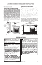
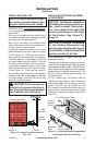
COMBUSTION AIR KIT MODEL AK4
The outside air kit may be installed on the
left side of the replace only. The vent can be
installed through any outside wall a minimum
of three feet below replace termination cap.
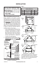
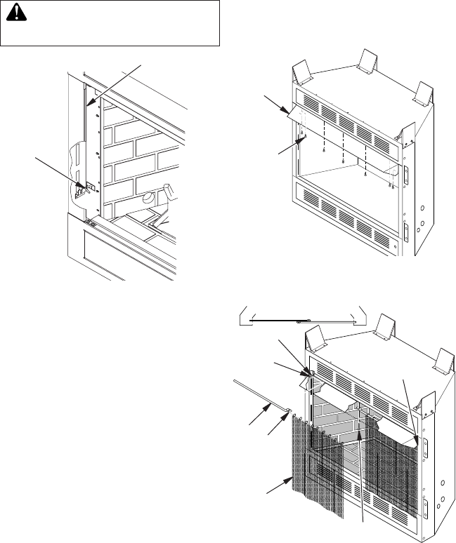
The handle to operate the damper door for the
outside air inlet will be located inside the left
“screen pocket” of the rebox (see Figure 20).
Pull the handle to open or push to close.
CAUTION: Air inlet ducts are
Figure 20 - Air Kit Handle Location
Air Kit
Handle
Screen Pocket
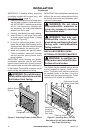
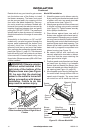
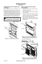
INSTALLING FIREPLACE HOOD
AND SCREEN
1. Attach hood to rebox using screws pro-
vided (see Figure 21).
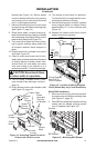
2. Insert each rod through all rings located
at top of screen.
3. Insert rst rod into rear hole in left side
of rebox. Fasten rod to rear hole near
center of rebox using #10 x 3/8" Phillips
screw provided (see Figure 22).
4. Insert other rod into front hole on right
side of rebox and fasten using remaining
Phillips screw.
Figure 21 - Screw and Hood Placement
(Model May Vary From Illustration)
Figure 22 - Installing Fireplace Screen
(Model May Vary From Illustration)
Screw
Rear Hole
Top View of Rod Layout
Rod
Front
Hole
Ring
Screen
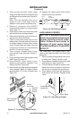
Identication
Label Location
Screws
Hood