


www.fmiproducts.com
125078-01B 7
C
B
A
D
E
F
G
3
2
1
4
5
6
7
Wall
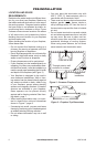
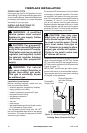
CLEARANCES
Minimum clearances to combustibles for the
replace are as follows:
*Back and sides 1"
Perpendicular walls 6"
Floor 0"
Ceiling to louver opening 42"
Front 36"
Top of Standoffs 0"
Vent (See venting instructions
for specic venting
clearances.)
Combustible material with a maximum thick-
ness of 5/8" may be ush with the top front
of replace.
* For back and sides of replace, do not pack
with insulation or other materials. 1" clearance
not required at nailing anges.
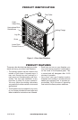
NOTICE: This replace is intend-
ed for use as supplemental heat.
Use this replace along with
your primary heating system.
Do not install this replace as
your primary heat source. If you
have a central heating system,
you may run system’s circulat-
ing blower while using replace.
This will help circulate the heat
throughout the house.
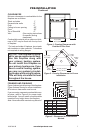
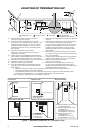
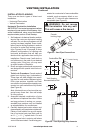
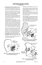
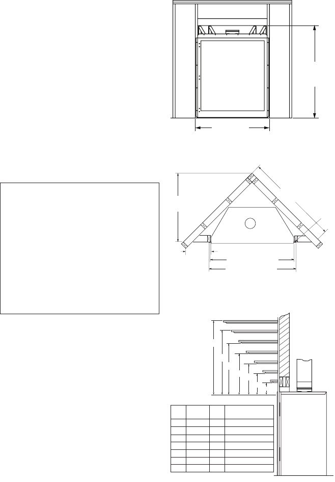
FRAMING AND FINISHING
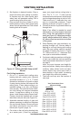
Figure 4 shows typical framing of this replace.
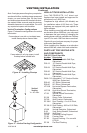
Figure 5 shows framing for corner installation.
All minimum clearances must be met.
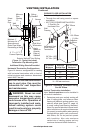
If you are using a separate combustible man-
tel piece, refer to Figure 6 for proper instal-
lation height. You can install noncombustible
mantels at any height above the replace.
Note: Noncombustible mantels may discolor!
PRE-INSTALLATION
Continued
43
1
/
4
"
(36")
47
1
/
4
"
(42")
41
1
/
2
"
(36")
48
1
/
2
"
(42")
Figure 4 - Framing Clearances with
Outside Air Flex Duct
Figure 5 - Framing Clearances for Corner
Installation
Figure 6 - Clearances for Combustible
Mantels
Ref.
Mantel
Depth Ref.
Mantel from
Top of Opening
1 14" A 16"
2 12" B 14"
3 10" C 12"
4 8" D 10"
5 6" E 8"
6 4" F 6"
7 2" G 4"
36
3
/
8
"
(36")
43
3
/
8
" (42")
43" (36"), 50" (42")
42" (36"), 49" (42")
15
3
/
4
"
(36")
19" (42")
51
3
/
8
"
(36")
61
3
/
4
" (42")
Nailing
Tabs