


www.fmiproducts.com
125311-01A 11
IMPORTANT: For natural gas, check gas line
pressure before connecting heater to gas line.
Gas line pressure must be no greater than
10.5" W.C.. If gas line pressure is higher,
heater regulator damage could occur.
CAUTION: For propane/LP
gas, never connect heater di-
rectly to the propane/LP supply.
This heater requires an external
regulator (not supplied). Install
the external regulator between the
heater and propane/LP supply.
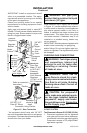
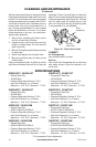
For propane/LP gas, the installer must supply
an external regulator. The external regulator will
reduce incoming gas pressure. You must reduce
incoming gas pressure to between 11" and 14"
W.C.. If you do not reduce incoming gas pres-
sure, heater regulator damage could occur. Install
the external regulator with the vent pointing down
as shown in Figure 14. Pointing the vent down
protects it from freezing rain or sleet.
CAUTION: Use only new, black
iron or steel pipe. Internally-tinned
copper tubing may be used in
certain areas. Check your local
codes. Use pipe of large enough
diameter to allow proper gas vol-
ume to heater. If pipe is too small,
undue loss of volume will occur.
Typical Inlet Pipe Diameters
16-18,000 Btu/hr models - 3/8" or greater
26-30,000 Btu/hr models - 1/2" or greater
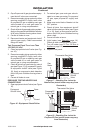
Installation must include equipment shutoff
valve, union and plugged 1/8" NPT tap. Locate
NPT tap within reach for test gauge hook up.
NPT tap must be upstream from heater (see
Figure 15, page 12).
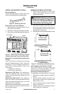
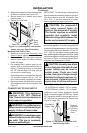
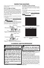
Mounting Base Feet to Floor
1. Remove front panel (see Removing Front
Panel of Heater, page 9).
2. Position heater with base feet in desired
location. Mark holes for drilling. Remove
heater with base.
3. For carpeted oors, make a small cut with
a sharp knife at marked locations prior to
drilling. If mounting base to a wood oor,
drill 1/8" diameter hole, 3/4" deep. (Do not
use anchors in wood oors).
If mounting base to a concrete oor, drill with
1/4" diameter concrete drill bit, 13/8" into
oor. Insert anchors completely into holes.
4. Reposition heater with base feet over holes.
Secure base to oor with wood screws. See
Figure 13.
CONNECTING TO GAS SUPPLY
WARNING: This appliance
requires a 3/8" NPT (National
Pipe Thread) inlet connection to
the pressure regulator.
WARNING: A qualied service
person must connect heater to gas
supply. Follow all local codes.
WARNING: For natural gas, never
connect heater to private (non-utility)
gas wells. This gas is commonly
known as wellhead gas.
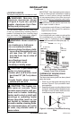
INSTALLATION
Continued
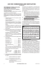
Propane/LP
Supply Tank
External
Regulator
with Vent
Pointing
Down
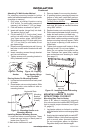
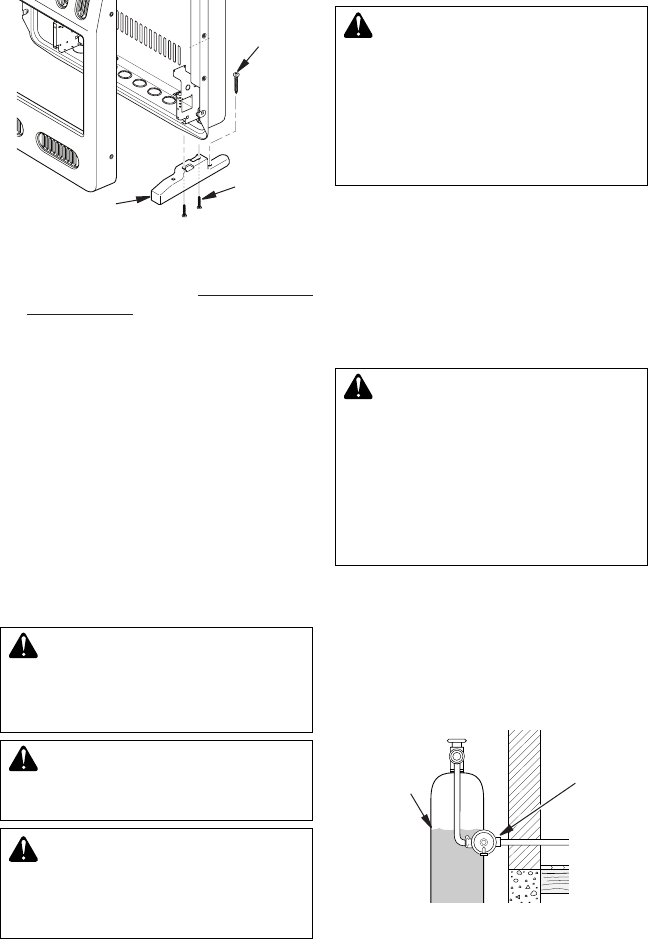
Figure 13 - Installing Base Feet (actual
heater may vary from illustration)
Figure 14 - Equipment Regulator with
Vent Pointing Down
3. Align holes in base foot with mounting holes
on bottom of cabinet (see Figure 13).
4. Secure base foot to heater using sheet
metal screws.
5. Repeat for other side.
Sheet
Metal
Screw
Wood
Screw
Base Foot