


www.fmiproducts.com
125311-01A8
LOCATING HEATER
This heater is designed to be mounted on a wall.
WARNING: Maintain the
minimum clearances shown
in Figure 4. If you can, provide
greater clearances from oor,
ceiling and joining wall.
You can locate heater on oor, away from
a wall. An optional oor mounting stand is
needed. Purchase the oor mounting stand
from your dealer. See Accessories, page 27,
if stand is not included with your heater.
WARNING: Never install the
heater
• in a bedroom or bathroom
• in a recreational vehicle
• where curtains, furniture, cloth-
ing or other ammable objects
are less than 36" (91.5 cm)
from the front, top or sides of
the heater
• as a replace insert
• in high trafc areas
• in windy or drafty areas
CAUTION: If you install the
heater in a home garage
• heater pilot and burner must
be at least 18" (45.7 cm) above
oor
• locate heater where moving
vehicle will not hit it
CAUTION: This heater cre-
ates warm air currents. These
currents move heat to wall sur-
faces next to heater. Installing
heater next to vinyl or cloth wall
coverings or operating heater
where impurities (such as, but
not limited to, tobacco smoke,
aromatic candles, cleaning uids,
oil or kerosene lamps, etc.) in the
air exist, may discolor walls or
cause odors.
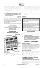
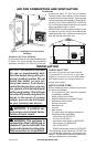
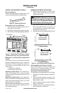
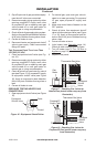
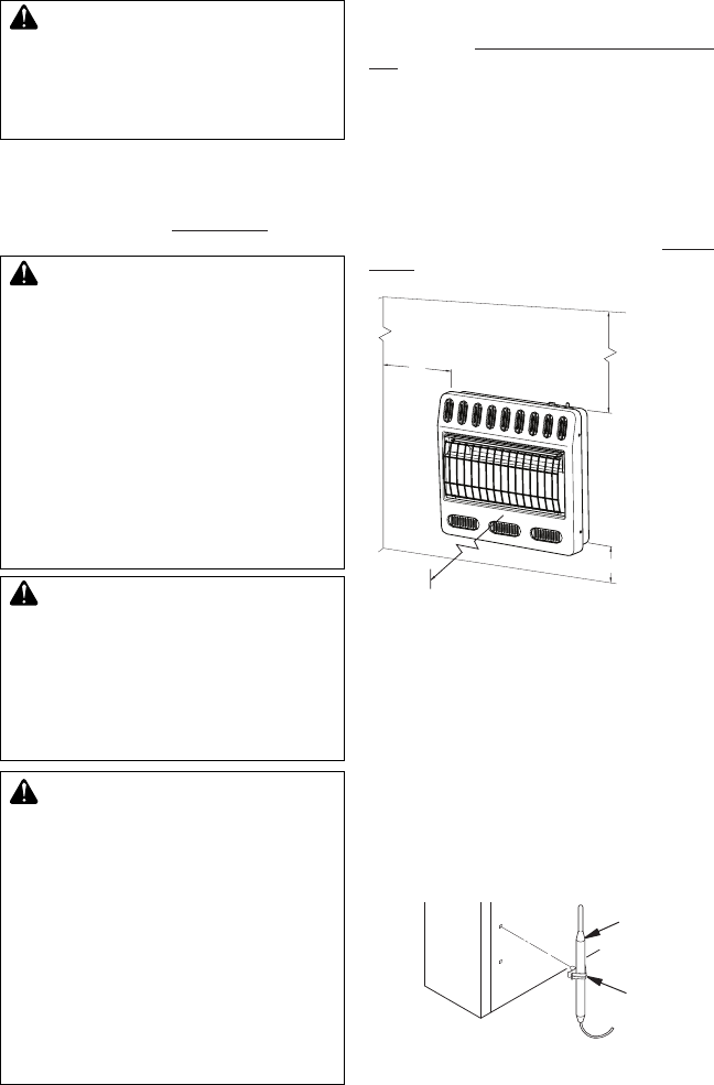
Figure 4 - Mounting Clearances As
Viewed From Front of Heater
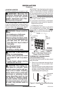
Figure 5 - Attaching Thermostat Sensing
Bulb
INSTALLATION
Continued
Minimum
From
Sides Of
Heater
2" (5.1 cm)
FLOOR
CEILING
36"
(91.5 cm)
Minimum
Minimum To
Top Surface
Of Carpeting,
Tile Or Other
Combustible
Material
Left
Side
Right
Side
10" (25.4 cm)
36"
(91.5 cm)
Clip
Thermostat
Sensing
Bulb
IMPORTANT: Vent-free heaters add moisture
to the air. Although this is benecial, installing
heater in rooms without enough ventilation
air may cause mildew to form from too much
moisture. See Air for Combustion and Ventila-
tion, page 5. If high humidity is experienced,
a dehumidier may be used to help lower the
water vapor content in the air.
For convenience and efciency, install heater
• where there is easy access for operation,
inspection and service
• in coldest part of room
If not included with your heater, an optional fan
kit is available from your dealer. See Acces-
sories, page 27. If planning to use fan, locate
heater near an electrical outlet (see page 16).
THERMOSTAT SENSING BULB
(Thermostat Models Only)
The thermostat sensing bulb has been placed
below the heater.
1. Place clip on thermostat sensing bulb as
shown in Figure 5. Clip is provided in hard-
ware package.
2. Snap clip into upper mounting hole as shown
in Figure 5. Mounting hole is located on lower
left edge on back of heater. Make sure ther-
mostat sensing bulb is pointing up.