


11
901846
OWNER’S MANUAL
INSTALLATION
Continued
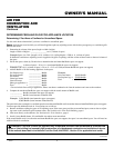
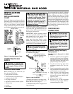
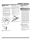
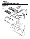
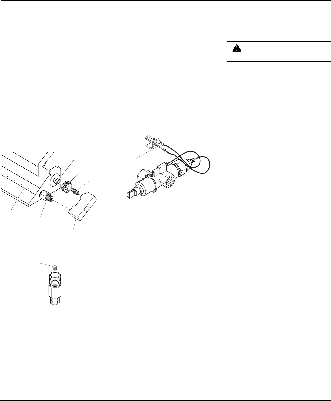
Figure 16 - Burner Inlet Fitting with
Injectors
BURNER
INLET
FITTING
Injector for
Natural Gas
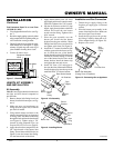
Figure 15 - Kit Assembly
Burner Inlet
Fitting
Front
Burner
Pipe
Nipple
Air Restrictor
Manifold
Block
Rear Burner Nozzle
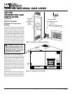
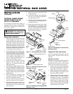
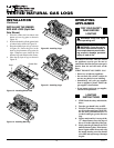
Figure 17 - Installing Propane/LP Pilot
Orifice
Pilot
Injector
Changing Pilot Orifice
The pilot is provided with a natural gas
orifice installed. For propane/LP gas you
must remove it and replace it with an pro-
pane/LP orifice. The hardware kit contains
an propane/LP orifice with a red stripe for
converting the pilot.
1. Gently loosen and remove the pilot
line connection from the bracket (see
Figure 17).
2. Replace the injector (see Figure 17)
with the propane/LP pilot injector with
the red stripe.
3. Replace and tighten the pilot line to the
bracket.
4. Continue with step 3 under Natural
Gas Installation, page 10.
TESTING BURNER FOR
LEAKS
1. Generously apply soapy solution to all
connections.
WARNING: Never check for
gas leaks with open flame.
2. Light the burner with the shutoff valve
no more than half open and holding a
match slightly in front of the pan (see
Lighting Instructions, page 12).
3. Inspect all connections for bubbles, raw
gas odor, or flame from any area other
than the burner (leaks). If leaks are de-
tected, shut off the gas valve immedi-
ately. Tighten, or reassemble the loose
connection(s) using pipe joint com-
pound until burner system is leak free.
4. When the burner is tested and leak free,
observe the individual tongues of flame
on the burner.
Note:
The burner design
includes more ports on the outside of the
bar. Make sure that all ports are clear
and producing flame evenly across the
burner. If any ports appear blocked, clear
them by removing the burner manifold
and reaming the ports with a modified
paper clip or other suitable tool.
5. When finished testing, turn the gas
shutoff valve OFF to extinguish all
flames.
ADDING PAN MATERIAL
1. Open the bag of ash bed material (ver-
miculite) and spread it evenly across
the burner pan to the top. You may over-
flow the front and sides of the pan to
cover the entire pan and connecting
hardware.
2. Open the glowing embers and evenly
cover the ash bed material (vermicu-
lite) in the burner pan.
4. Apply thread sealant compound to the
3/8" male threads of the burner inlet
fitting. Thread the manifold block (see
Figure 15) onto the burner inlet fitting.
Use the bottom hole of the block.
5 . Apply thread sealant to the 1/8" brass
pipe nipple and thread it into the mani-
fold block (see Figure 15). Tighten with
a 7/16" wrench.
6. Slip the air restrictor over the 1/8" pipe
nipple. Apply thread sealant to the male
threads and install the rear burner injec-
tor provided with the GA9003 (see chart
on page 7) onto the fitting. Tighten with
a 9/16" wrench. Proceed with step 7,
page 9 in Hearth Kit Assembly.