


11
105224
OWNER’S MANUAL
CONNECTING TO GAS
SUPPLY
WARNING: A qualified ser-
vice person must connect heater
to gas supply. Follow all local
codes.
CAUTION: Never connect
heater directly to the propane/LP
supply. This heater requires an
external regulator (not supplied).
Install the external regulator be-
tween the heater and propane/LP
supply.
Installation Items Needed
Before installing heater, make sure you have
the items listed below.
• external regulator (supplied by installer,
see above)
• piping (check local codes)
• sealant (resistant to propane/LP gas)
• manual shutoff valve *
• test gauge connection *
• sediment trap
• tee joint
• pipe wrench
* An A.G.A. design-certified manual shutoff
valve with 1/8" NPT tap is an acceptable
alternative to test gauge connection.
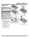
The installer must supply an external regu-
lator. The external regulator will reduce
incoming gas pressure. You must reduce
incoming gas pressure to between 11 and 14
inches of water. If you do not reduce incom-
ing gas pressure, heater regulator damage
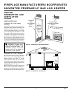
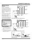
could occur. Install external regulator with
the vent pointing down as shown in Figure
13. Pointing the vent down protects it from
freezing rain or sleet.
INSTALLATION
Continued
Fitting
Flexible Gas
Hose (if allowed
by local codes)
WARNING: Never connect
heater to private (non-utility) gas
wells. This gas is commonly
known as wellhead gas.
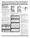
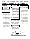
Installation must include a manual shutoff
valve, union, and plugged 1/8" NPT tap.
Locate NPT tap within reach for test gauge
hook up. NPT tap must be upstream from
heater (see Figure 14).
Apply pipe joint sealant lightly to male
threads. This will prevent excess sealant
from going into pipe. Excess sealant in pipe
could result in clogged heater valves.
CAUTION: Use only new,
black iron or steel pipe. Inter-
nally-tinned copper tubing may
be used in certain areas. Check
your local codes. Use pipe of 1/2"
diameter or greater to allow
proper gas volume to heater. If
pipe is too small, undue loss of
pressure will occur.
Install sediment trap in supply line as shown
in Figure 14. Locate sediment trap where it
is within reach for cleaning. Locate sedi-
ment trap where trapped matter is not likely
to freeze. A sediment trap traps moisture
and contaminants. This keeps them from
going into heater controls. If sediment trap
is not installed or is installed wrong, heater
may not run properly.
CAUTION: Use pipe joint seal-
ant that is resistant to liquid pe-
troleum (LP) gas.
CAUTION: Avoid damage to
control. Hold fitting with wrench
when connecting it to gas piping
and/or fittings.
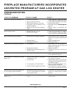
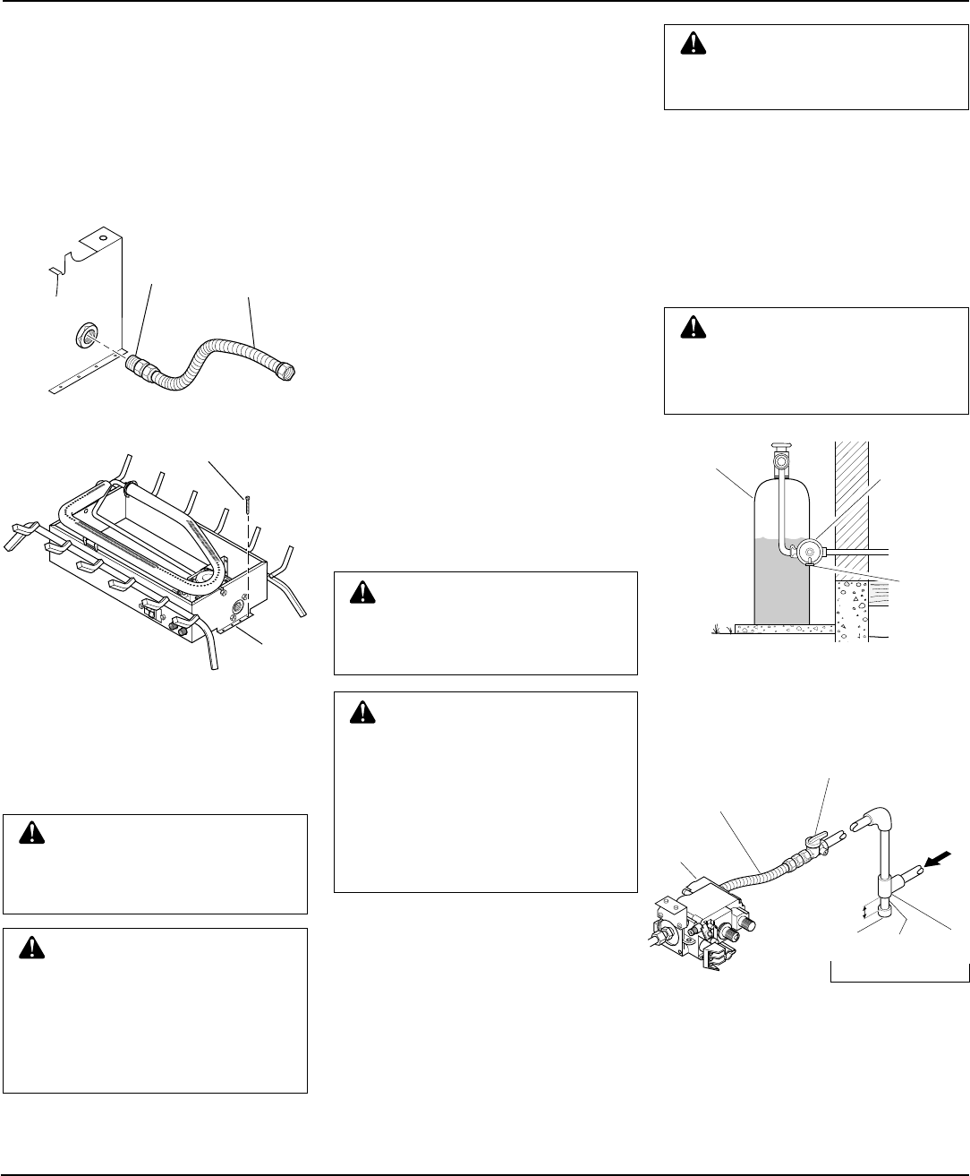
Figure 13 - External Regulator With Vent
Pointing Down
Propane/LP
Supply
Tank
External
Regulator
Vent
Pointing
Down
Figure 14 - Gas Connection
* Minimum inlet pressure for purpose of
input adjustment.
3" Minimum
Gas
Control
A.G.A. Design-
Certified Manual
Shutoff Valve With
1/8" NPT Tap
Approved
Flexible Gas
Hose (if allowed
by local codes)
O
F
F
P
I
L
O
T
O
N
H
I
L
O
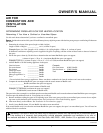
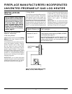
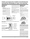
Figure 11 - Attaching Flexible Gas Hose
to Heater
Figure 12 - Attaching Base Assembly to
Fireplace Floor
Masonry Screw
Mounting
Flanges
Continued
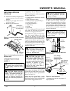
10. Attach base assembly to fireplace floor
using two masonry screws (in hardware
package).
11. Connect to gas supply. See Connect-
ing To Gas Supply.
12. Replace logs on heater base.
Cap Pipe Tee
Nipple Joint
Sediment
Trap
From External
Regulator (11"
W.C.* to 14"
W.C. Pressure)