


13
105194
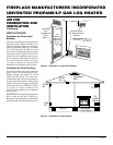
OWNER’S MANUAL
A
U
T
O
O
F
F
O
N
A
U
T
O
O
F
F
O
N
O
F
F
P
I
L
O
T
O
N
H
I
L
O
H
I
L
O
INSTALLATION
Continued
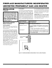
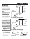
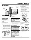
Figure 16 - Checking Gas Joints
WARNING: Failure to posi-
tion the parts in accordance with
these diagrams or failure to use
only parts specifically approved
with this heater may result in
prop-
erty damage or personal injury.
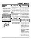
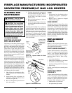
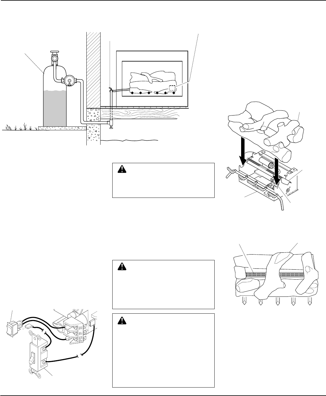
INSTALLING LOGS
It is very important to install the logs exactly
as instructed. Do not modify logs. Only use
logs supplied with heater.
1. Place one-piece log set on grate to fit
as illustrated in Figure 18. Make sure
bottom of front log is in front of “U”-
shaped cutout in center of chassis. Log
will fit securely on chassis.
IMPORTANT:
Make sure log does not
cover any burner ports.
2. Place lava rock around base of heater
if desired.
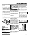
Figure 18 - Installing Heat Majic™ One-
Piece Log Set
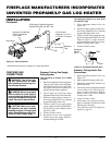
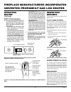
Figure 19 - Installing Heat Majic™ One-
Piece Log Set (Top View)
One Piece Log Set
Burner
Ports
One Piece
Log Set
Burner
"U"-shaped
Cutout in
Chassis
Chassis
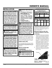
Control Valve
Location
Propane/LP
Supply Tank
Equipment
Shutoff Valve
CAUTION: After installation
and periodically thereafter, check
to ensure that no flame comes in
contact with any log. With the
heater set to High, check to see if
flames contact any log. If so, re-
position logs according to the
log installation instructions in this
manual. Flames contacting logs
will create soot.
INSTALLING GWMS2
(OPTIONAL) WALL
MOUNTED SWITCH
Items Included for Installation
• Switch
• Switch Cover (with screws)
• 25 Ft. Wire
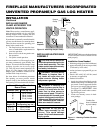
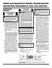
Connecting to Log Set
1. Connect one terminal of 25 ft. wire to
bottom contact of switch located on
heater front control panel (see Figure 17).
2. Connect remaining wire terminal to the
“TH” terminal on the control valve (see
Figure 17).
3. Route the 25 ft. wire to a convenient
location.
WARNING: Do not connect
the switch to a power source.
Electrical shock and/or fire haz-
ard will occur.
IMPORTANT:
The wire may be shortened
but must not be lengthened.
4. Connect one bare wire end to each of
the terminals of the wall switch.
5. Install the wall switch and cover in
the wall.
Figure 17 - Connecting the Wire Terminals
Wall Switch
Switch