


www.fmiproducts.com
120926-26C 11
CLEANING AND MAINTENANCE
Continued
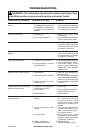
REPLACING FLAME GENERATION
LED
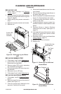
1. Follow steps 1 through 4 under Cleaning
Firebox, page 8
2. Remove screws from each side of log that
secures log to base and remove log (see
Figure 10, page 8).
3. Remove screws from sides and back of
bottom panel of rebox.
4. Gently lay unit on its back.
5. There are several wires attached to bot-
tom panel. Carefully remove panel.
6. Disconnect wires from motor and LED
drum assembly.
7. Remove screws from bottom panel to
remove assembly.
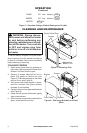
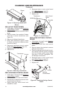
8. If motor on assembly fails, loosen clamps
(see Figure 17). Remove screws from
motor. Hold universal joint while removing
motor and discard.
9. Install new motor. Slide motor shaft into
universal joint and tighten clamps.
10. Hold LED drum assembly in place on
bottom panel and replace screws.
11. Reattach wires to motor and LED drum.
Note: LED drum wires are polarity sensi-
tive and must be connected correctly.
White wire plugs onto left terminal and red
wire plugs onto right terminal. Motor wires
can be connected to either terminal.
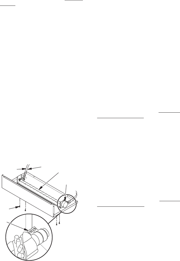
LED Drum
Assembly
Screws
White Wire
Red
Wire
Figure 17 - Flame Generation LED Drum
Assembly
Motor
12. Replace replace bottom panel. Set re-
place upright and replace screws.
13. Replace log, glass and bracket.
14. Reinstall replace and replace trim.
CLEANING OR REPLACING BACK
SCREEN (GLASS)
1. The glass is cleaned in the factory during
assembly. During shipment, installation,
handling, etc. glass surface may collect
dust particles. These can be removed
by bufng lightly with a clean damp cloth
(water only). Glass should be completely
dried with a lint free cloth or paper towel.
2. In the event of glass breakage, vacuum all
remaining glass pieces with a shop vac. DO
NOT VACUUM WHILE PIECES ARE HOT.
Replace glass only with replacement part
specically for this heater. Never substitute
material. Only fully tempered soda lime
safety glass may be used on this heater.
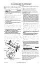
3. To access glass to clean or replace,
follow steps 1 and 7 under Replacing
Flame Generation LED. Set aside bottom
panel.
4. Remove screws securing log base to unit.
Carefully remove log base from unit.
5. Using gloves, gently remove glass panel
by sliding it toward you. There is a rubber
bumper on each corner of glass.
6. Clean glass as instructed in step 1 or
replace glass.
7. Using gloves, reinstall glass by gently
sliding, smooth side toward replace front,
into brackets on either side that hold glass
in place.
8. Replace log base.
9. Follow steps 11 and 14 under Replacing
Flame Generation LED.
TEChNICAL SERVICE
You may have further questions about instal-
lation, operation or troubleshooting. If so,
contact FMI PRODUCTS, LLC at 1-866-328-
4537. When calling please have your model
and serial numbers of your heater ready. This
information is located on the inside of the
control panel door (Figure 2, page 4).
You can also visit our web site at
www.fmiproducts.com.
Clamps