57
Ref. 185040646 MR730/720/700/480 Technical Manual ¯ Revision F ¯ Issued March 2001
3 Connect the Heater Wire cable to the humidifier.
4 If a gas supply is used, set to 5- 10 l/minute, if no gas supply used, the breathing tube should be supported
from the patient end so that it drops vertically over its entire length to the top of the chamber.
E.2.3 DYNAMIC TEST SEQUENCE (MR730/720/700)
1 Turn the humidifier on, ensure the heater wire LED is on for a MR720 or MR730.
2 Adjust set temperature to 36.0 ± 0.1 °C and Chamber Control to 0.
3 NOTE: At low ambient temperatures (below 22 °C) a low temperature alarm may occur, if this occurs, press mute
and restart the test , the breathing circuit will eventually warm up and the humidifier will start controlling.
4 Check after 30 minutes:
Digital display is 36.0 ± 0.3 °C
Chamber outlet temperature is 36.0 ± 2.0 °C
If the unit is alarming or has not reached 36 ± 0.3 °C, press the mute button if necessary and leave for a further
15 minutes.
5 Then check the following in ‘Engineering Mode’ (see appendix A2):
set 36 ± 0.1 °C
offset 0
Edc ≥ 0
Cdc ≥ 0
hp ≥ 36 °C
5 If unit passes this test it is controlling correctly and can be put back in use.
6
E.3 PERFORMANCE CHECK (MR480)
E.3.1 EQUIPMENT SETUP
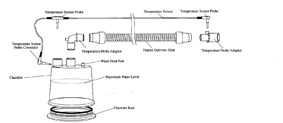
Set up a non heated breathing circuit, see typical setup below:
Setup Notes:
♦ Patient delivery tubing can be single use or reusable.
♦ A gas supply of 2 – 10 l/minute to the chamber is recommended, if no gas supply is used, then the breathing circuit
must be 22mm diameter to ensure adequate airflow.
♦ Use a dual airway temperature sensor, such as 900MR560.
♦ Use a Fisher and Paykel humidification chamber, such as a MR200 series, filled with cold water to maximum level (not
a MR290).


