


SPECIAL REQUIREMENTS FOR INTERCONNECTED ALARMS
•
Failur
e to meet any of the above requirements could damage
the units and cause them to malfunction, removing your
pr
otection.
• AC and AC/DC Smoke/CO Alarms can be interconnected.
Under AC power
, all units will alarm when one senses smoke
or CO. When power is interrupted, only the AC/DC units in
the series will continue to send and receive signals.
AC power
ed Smoke/CO Alarms will not operate. See “Smart
Interconnect” Feature.
Inter
connected units can provide earlier warning of a Smoke/CO problem
than stand-alone units, especially if the problem starts in a remote area of
the dwelling. If any unit in the series senses Smoke/CO, all units will alarm.
To determine which Smoke/CO Alarm initiated an alarm, refer to the table.
During an Alarm:
On Initiating Alarm(s) – Red LED(s) flashes (flash) rapidly
On All Other Alarms – Red LED is Of
f
After an Alar
m (Latching):
On Initiating Alarm(s) – Gr
een LED(s) On, Red LED(s) flash once every 5 seconds
On All Other Alarms – Green LED(s) On, Red LED(s) is Off
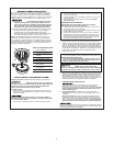
Compatible Interconnected Units
Interconnect units within a single family residence only. Otherwise all
households will experience unwanted alarms when you test any unit in the
series. Interconnected units will only work if they are wired to compatible
units and all requirements are met. This unit is designed to be compatible
with:
BRK Electronics
®
Smoke Alarm Models 9120, 9120B, 7010, 7010B,
7020B, 4120, 4120B, 4120SB, 4919, 2002RAC, 100S, 5919, 5919TH;
BRK Electronics
®
Heat Alarm Models HD6135F, HD6135FB; BRK
Electronics
®
CO Alarm Models CO5120BN, CO5120PDBN; Smoke/CO
Alarm Model SC6120B, SC9120B; and
First Alert
®
Smoke Alarm Models
SA4120, SA4120B, SA4121B, SA4919B, SA100B, SC7010B, SC7010BV;
Accessory devices models RM3, RM4, SL177.
Interconnected units must meet ALL of the following requirements:
• A maximum of 18 compatible BRK Electronics
®
Smoke, Heat or CO
Alarms may be interconnected. No more than 12 of the 18 can be
Smoke Alarms per NFPA 72.
• The same fuse or circuit breaker must power all interconnected units.
• The total length of wire interconnecting the units should be less
than 1000 feet (300 meters). This type of wire is commonly available
at Hardware and Electrical Supply stores.
• All wiring must conform to all local electrical codes and NFPA 70 of
the National Electrical Code. Refer to NFPA 72, NFPA 101, and/or
your local building code for further connection requirements.
6
7
8
4
3
1
5
4
3
1
5
2
A
B
}
}
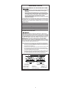
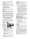
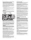
A. Unswitched 120VAC B. To Additional Alarms,
60 Hz source Maximum = 18 Alarms
1. Smoke/CO Alarm
2. Ceiling or W
all
3. Power Connector
4. Wire Nut
5. Junction Box
6.
Neutral Wir
e (White)
7. Interconnect Wire
(Orange)
8. Hot Wir
e (Black)
INSTALLATION, Continued
4