Architectural Specifications
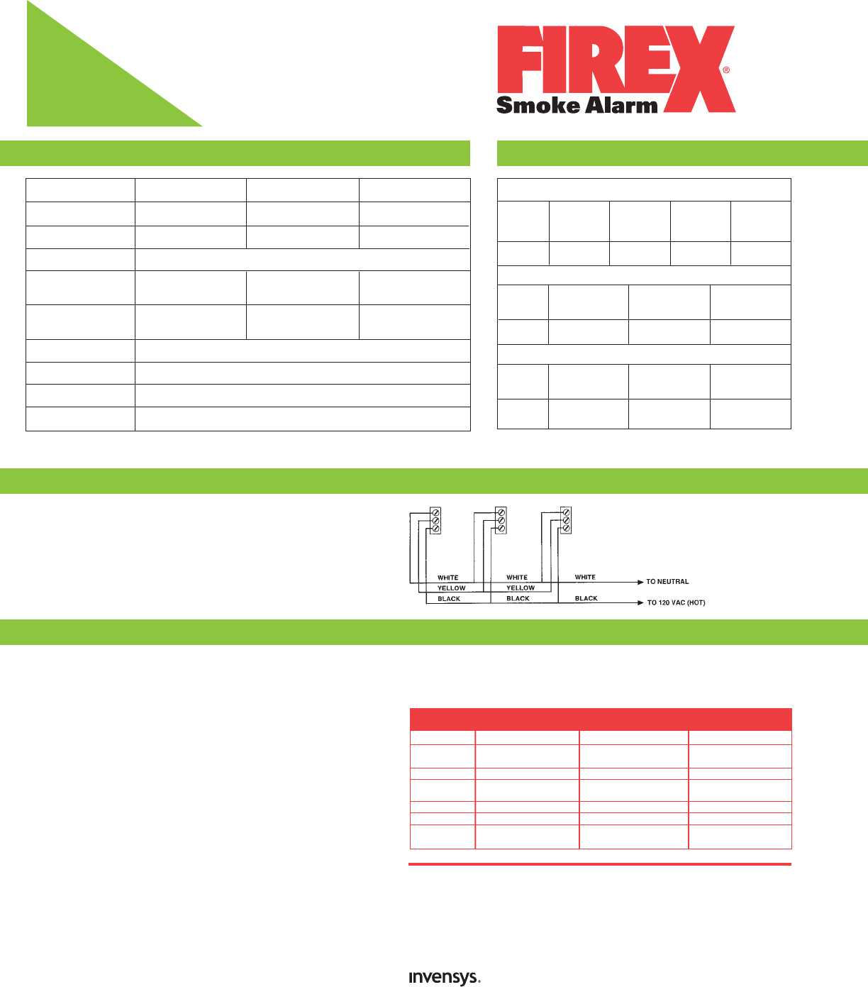
Installation of Smoke Alarm
Photoelectric
Shipping Specifications
Technical Specifications
Item
Model
Product Weight
Operating Temperature
Electrical
Rating
Alarm Point
(Canadian)
Horn Output
Listing
Detection Type
Humidity Rating
4480
PAD
8 ounces
120V AC, 60HZ, 50mA max,
9 Volt Battery Backup
obs. 2.3 ± .95%/ft.
Ind. Ctn. Dim.
Master Ctn. Qty.
Master Ctn. Dim.
Master Ctn. Wt.
Pallet Quantity
Pallet Dim.
4480
5-1/8” x 5-1/8” x 1-1/2”
13cm x 13cm x 3.8cm
12
10-3/4” x 10-1/2” x 5-3/4”
27.3cm x 26.7cm x 14.6cm
6.4 lbs / 2.9kg
864
40”L x 48”W x 40.5”D
102cm x 122cm x 103cm
484, 484(C)
5-1/8” x 5-1/8” x 1-1/2”
13cm x 13cm x 3.8cm
12
10-3/4” x 10-1/2” x 5-3/4”
27.3cm x 26.7cm x 14.6cm
4.5 lbs / 2kg
864
40”L x 48”W x 40.5”D
102cm x 122cm x 103cm
480, 480(C)
4-1/8” x 4-1/8” x 1-1/2”
10.5cm x 10.5cm x 3.8cm
12
9-3/8” x 8-3/4” x 4-7/8”
23.8cm x 22.2cm x 12.4cm
3.5 lbs / 1.6kg
2160
48”L x 40”W x 48.3”D
122cm x 102cm x 103cm
This smoke alarm should be installed in accordance with NFPA’s Standard 72
(National Fire Protection Association, Batterymarch Park, Quincy, MA 02269) and
any local codes that apply. For the AC and AC/DC direct wire smoke alarms use
#18 AWG minimum solid or stranded wire. When interconnecting, maximum wire
length between any two is 1,500 feet for #18 AWG or 4,000 feet for #14 AWG
(20 OHMS loop resistance). DO NOT connect to any other type or model of heat
or smoke alarm. Connect smoke and heat alarms to a single AC branch circuit. If
local codes do not permit, be sure the neutral wire is common to both phases.
The 4480 shall be 1-3/8” high and 5” wide, powered by a 120V AC, 60Hz source
with a 9 volt battery back-up. Nominal sensitivity shall be measured by U.L. at
obs. 2.3 ± .95%/ft. A green continuous power on indicator shall be a built-in
light emitting diode (LED) in the standby condition; a second red blinking LED
shall indicate that a sufficient 9-volt battery back-up is present; when activated,
the initiating alarm red LED shall flash while the interconnected alarms remain
extinguished. A 70 day low battery signal shall be included.
The 484(C) shall be 1-3/16” high and 4-7/8”wide powered by a 120V AC, 60Hz
source. Nominal sensitivity shall be measured by U.L. at obs. 2.2 ± 1.2%/ft.
and by U.L.C. at obs. 2.2 ± .75%/ft. A power-on indicator shall be a built-in LED
which blinks once per minute in the standby condition; when activated, the
initiating alarm LED shall flash while the interconnected alarms remain
extinguished.
The 4480 and the 484(C) shall be rated at no more than 0.5W in standby and
have 100% solid state alarm circuits over an input range of 100-130V AC. The
alarm shall mount to a single gang box, 4” octagon junction box, or a square-to-
round drywall ring without screw removal. It shall have a Quick Connect molded
harness and pigtail wiring.
The 480(C) shall be 1” high and 4” wide powered by a 9V DC battery source.
Nominal sensitivity shall be measured by U.L. at obs. 2.2 ± 1.2%/ft. and by
U.L.C. at obs. 2.2 ± .75%/ft. 100% solid state alarm circuits over an input range
of 6.8-10V DC. A power-on indicator shall be a built-in LED which blinks once
per minute in the standby condition and a 30 day low battery signal shall be
included.
All Firex photoelectric smoke alarms shall be a Styleline design
TM
and have a
photoelectric sensor. Operating temperature range shall be between 40° and
100°F (4°-38°C) and relative humidity range between 10%-93%. The test
switch shall electronically activate the chamber to simulate smoke and check
for proper operation. The electric horn shall have a level of 85 decibels at
484(C)
PG
5.5 ounces
40˚–100˚F 4˚-38˚C
120V AC, 60HZ, 50mA
obs. 2.2 ± 1.2%/ft.
(obs. 2.2 ± .75%/ft.)
85 decibels at 10 feet
UL 217 and ULC S531
Photoelectric Chamber
10%-93%
480(C)
PB
4.2 ounces
9 Volt DC Battery Powered
obs. 2.2 ± 1.2%/ft.
(obs. 2.2 ± .75%/ft.)
*Heat alarm item. Interconnectable up to 12 Firex AC/DC smoke alarms and
6 Firex heat alarms.
Interconnect Quantities
Item
(Model)
Quantity
Item
(Model)
Quantity
Item
(Model)
Quantity
4480
4480
(PAD)
≤12
4518
(ADC)
≤12
4418
(AD)
≤12
5700*
(ADH)
≤12
484
484
(PG)
≤12
406
(G)
≤6
484(C)
484(C)
(PG)
≤12
418(C)
(G)
≤12
406(C)
(G)
≤6
41216
(GC)
≤12
10 feet and all units have a separate mounting bracket. Items 4480, 484, 480 shall
meet the requirements of U.L. 217 and items 484(C) and 480(C) shall meet the
requirements of U.L.C. S531.
Controls Americas
191 E. North Avenue
Carol Stream Illinois 60188 USA
Customer Service Telephone +1 800 951 5526
Customer Service Facsimile +1 630 260 7299
iccacustomerservice@invensys.com
For Technical Service
Telephone +1 800 445 8299
Facsimile +1 630 260 7243
technicalservice@invensys.com
www.icca.invensys.com
©2005 Invensys Controls Americas - #150-1358E


