


2. WIRING - Another important difference in the replacement of an “ESU” model with a new “S”
series humidifier is the wiring connections. On the “ESU” the humidity control was connected to the
two ‘WHITE” wires on the molded plug. When upgrading to the “S” series, simply cut the two
white wires and connect them to the two “H” terminals on the top of the front cover.
The blower (fan) interlock was connected via the two red wires on the old “ESU” model and usually
incorporated a field installed transformer and interlocking relay. Just cut the two red wires and
connect them to the “R” and “G2” terminals on the top of the front cover. In this method you can
reuse the field relay and transformer which were originally installed with the ESU.
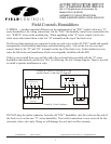
If this is a new install then you can fully utilize the on board relay provided with the “S” series
humidifier and interlock your blower “fan” by following the low voltage diagram. There is no need
to install a separate transformer or relay.
DO NOT plug the molex connector from the old “ESU” humidifier, into the socket on the side of
the front cover on the new “S” series humidifier. That socket connection is now reserved for the
automatic drain valve only. Doing so will damage the unit and void the warranty.
2
S2000 & S2020 T ypical Wir ing
and Blower I nter lock Diagr am
Furnace
S2000 & S2020 Humidifier
Humidistat
G1 R G2 H H
Typical
Thermostat
G YWR
G YWR
H eat & Cool System
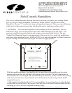
Field Controls Humidifiers
AN-137 Replacement Instructions for
Models ESU14 & ESU20
SUPPLEMENT TO THE ELECTRONIC STEAM
POWER HUMIDIFIERS MODEL #S2000 AND S2020
P/N 090376A0137 REV. D 10/2011 Copyright © 2011, Field Controls Inc., All Rights Reserved
Field Controls Inc. 2630 Airport Road Kinston, NC 28504 PH: 252.522.3031 FAX: 252.522.0214