


Page 2
improving the range of effective conditions.
ClearWave™
The ClearWave™ water conditioning system operates on similar principles as the magnets and electrostatic devices. But
unlike those previously mentioned, the ClearWave™ uses microprocessor technology to electronically generate inaudible
wave-forms which help keep calcium carbonate particles (scale) dissolved or suspended in water. With ClearWave™, the
electric field generated is always being applied to the water, while a magnetic field relies on the movement of water to
produce the electric potential changes.
Low frequency waveforms are emitted through two coiled wires attached to the outside of the water pipe. As a result of
these waveforms, the two coils are constantly inducing a voltage into the water in the area of the ClearWave™. When
one coil induces a positive voltage the other coil induces a counteracting negative voltage. This electric field causes the
calcium or magnesium to remain in solution or suspension and the treated water continues to dissolve scale as it flows
downstream. Over time, the ClearWave™ treated water helps solve hard water problems in the entire system, including
pipes, water heaters, showerheads, and appliances. The ClearWave™ is the state-of-the-art in electronic water
conditioning. The ClearWave™ microprocessor-controlled technology continually varies its frequency, affecting the
widest range of mineral concentrations and other variables that cause “hard water” problems.
The length of time required to alter the characteristics of the lime scale is dependent on the mineral makeup of the water
being treated. The mineral makeup of the water can impact the operation of the ClearWave™’s electrical field. A high
concentration of iron (soluble and insoluble) causes a disruption and weakening of the electrical field, reducing the
effectiveness on scale reduction. Under these conditions an iron removal system is required to filter out the iron prior the
ClearWave™. Additionally, if the water is excessively hard (greater than 25 grains), the ClearWave™ is often less
effective.
TESTING FOR HARDNESS AND IRON LEVELS
High Iron Concentration
A high concentration of iron (soluble and insoluble) causes a disruption and weakening of the ClearWave™’s electrical
field, reducing its effectiveness on scale reduction. Under these conditions an iron removal system is required to filter out
the iron prior to the ClearWave™. We recommend an iron removal system for total iron levels above 0.3 ppm (parts per
million). Contact your local health department or water authorities for testing your water
Water Hardness
On hardness levels above 250 ppm or 15 gpg, two ClearWave™ units should be mounted in series on the incoming water
pipe. The maximum hardness level the ClearWave™ will effectively work on is 425 ppm or 25 gpg. Above these levels,
the ClearWave™ should be used in conjunction with a tradition ion exchange water softener to remove hardness and
condition the water. This allows you to minimize the salt used to remove the hardness and maintain the cost saving
benefits of the ClearWave™ water-conditioning system.
INSTALLATION
WHERE TO INSTALL THE CLEARWAVE™
1. For water supply applications, locate where the main water supply pipe enters the home or building. Point
of use applications such as dishwashers, ice makers, boilers, water heaters etc., attach the ClearWave™
unit to the water supply line to that particular appliance. For long system piping lengths or high level
calcium water, mount a CW-HD-1 to point of use appliances.
2. Find a suitable location to install the ClearWave™ on the water supply pipe before the piping branches off
to supply water throughout the building.
H
OW TO INSTALL THE CLEARWAVE™
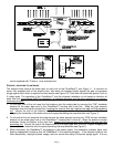
1. One set of mounting brackets are provided, for mounting the ClearWave™ onto 3 inch to 6 inch water
pipes or wall mounted near the selected pipe area. Mount the mounting brackets to the base of the
ClearWave™ by using the screws provided. Mount the ClearWave™ onto the pipe with wire ties or to the
wall with appropriate fasteners. (see Figure 1) For pipe mounting, the wall mount tabs should be removed
from the mounting brackets. (see Figure 2)
2. Plug the antennas into each end of the housing, to the appropriate wire wrap connections (e.g. “CW” for
clockwise wrapping and “CCW” for counter clockwise wrapping). If longer wires are needed, up to 50 feet
of 12Ga stranded wire can be added to the antenna wires with an insulated butt end wire connector or they